Qt Quick 3D - Simple Skinning Example
Demonstrates how to render a simple skinning animation in Qt Quick 3D.

Generally most skin animations will be designed by modeling tools, and Quick3D also supports glTF formats through the Balsam importer and Qt Design Studio. This example shows how each property is used for the skin animation in Quick3D.
Note: All the data in this example come from gfTF-Tutorial Skins.
Make a skinning geometry.
To use custom geometry data, we will define a geometry having positions, joints, weights, and indexes.
Q_OBJECT
QML_NAMED_ELEMENT(SkinGeometry)
Q_PROPERTY(QList<QVector3D> positions READ positions WRITE setPositions NOTIFY positionsChanged)
Q_PROPERTY(QList<qint32> joints READ joints WRITE setJoints NOTIFY jointsChanged)
Q_PROPERTY(QList<float> weights READ weights WRITE setWeights NOTIFY weightsChanged)
Q_PROPERTY(QList<quint32> indexes READ indexes WRITE setIndexes NOTIFY indexesChanged)
Each position is a vertex position and each vertex has 4 joints' indexes and corresponding weights.
Set up skinned data in QML
Position data and indexes
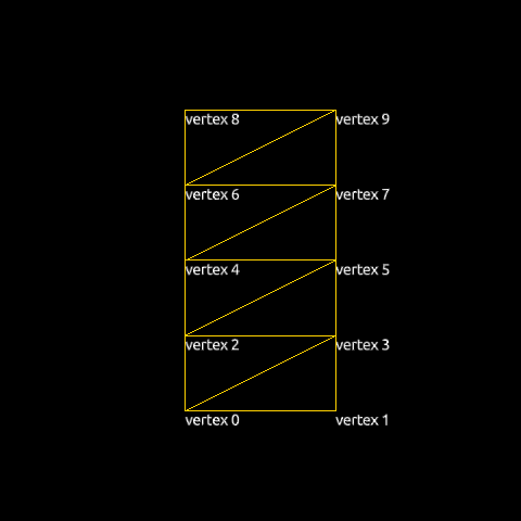
We will draw 8 triangles with 10 vertexes. The table below shows the QML code and a visualization of the vertexes.
| QML Code | Visualized |
|---|---|
positions: [ Qt.vector3d(0.0, 0.0, 0.0), // vertex 0 Qt.vector3d(1.0, 0.0, 0.0), // vertex 1 Qt.vector3d(0.0, 0.5, 0.0), // vertex 2 Qt.vector3d(1.0, 0.5, 0.0), // vertex 3 Qt.vector3d(0.0, 1.0, 0.0), // vertex 4 Qt.vector3d(1.0, 1.0, 0.0), // vertex 5 Qt.vector3d(0.0, 1.5, 0.0), // vertex 6 Qt.vector3d(1.0, 1.5, 0.0), // vertex 7 Qt.vector3d(0.0, 2.0, 0.0), // vertex 8 Qt.vector3d(1.0, 2.0, 0.0) // vertex 9 ] indexes: [ 0, 1, 3, // triangle 0 0, 3, 2, // triangle 1 2, 3, 5, // triangle 2 2, 5, 4, // triangle 3 4, 5, 7, // triangle 4 4, 7, 6, // triangle 5 6, 7, 9, // triangle 6 6, 9, 8 // triangle 7 ] |
|
Joints and weights data
Every vertex needs to specify the indexes of the joints that should have an influence on it during the skinning process. For each vertex we store these indexes as 4D vectors (Qt limits the number of joints that may influence a vertex to 4). Our geometry will have just two joint nodes (0 and 1), but since we use 4D vectors we set the remaining two joint indexes and their weights to 0.
joints: [
    0, 1, 0, 0, // vertex 0
    0, 1, 0, 0, // vertex 1
    0, 1, 0, 0, // vertex 2
    0, 1, 0, 0, // vertex 3
    0, 1, 0, 0, // vertex 4
    0, 1, 0, 0, // vertex 5
    0, 1, 0, 0, // vertex 6
    0, 1, 0, 0, // vertex 7
    0, 1, 0, 0, // vertex 8
    0, 1, 0, 0  // vertex 9
]
Corresponding weight values are as below.
weights: [
    1.00, 0.00, 0.0, 0.0, // vertex 0
    1.00, 0.00, 0.0, 0.0, // vertex 1
    0.75, 0.25, 0.0, 0.0, // vertex 2
    0.75, 0.25, 0.0, 0.0, // vertex 3
    0.50, 0.50, 0.0, 0.0, // vertex 4
    0.50, 0.50, 0.0, 0.0, // vertex 5
    0.25, 0.75, 0.0, 0.0, // vertex 6
    0.25, 0.75, 0.0, 0.0, // vertex 7
    0.00, 1.00, 0.0, 0.0, // vertex 8
    0.00, 1.00, 0.0, 0.0  // vertex 9
]
Skeleton and Joint hierarchy
For skinning, we add a skeleton property to the Model:
skeleton: Skeleton {
    id: qmlskeleton
    Joint {
        id: joint0
        index: 0
        skeletonRoot: qmlskeleton
        Joint {
            id: joint1
            index: 1
            skeletonRoot: qmlskeleton
            eulerRotation.z: 45
        }
    }
}
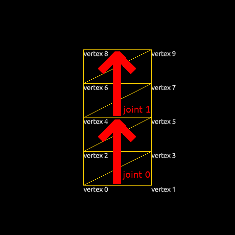
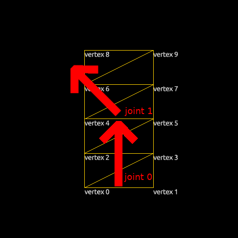
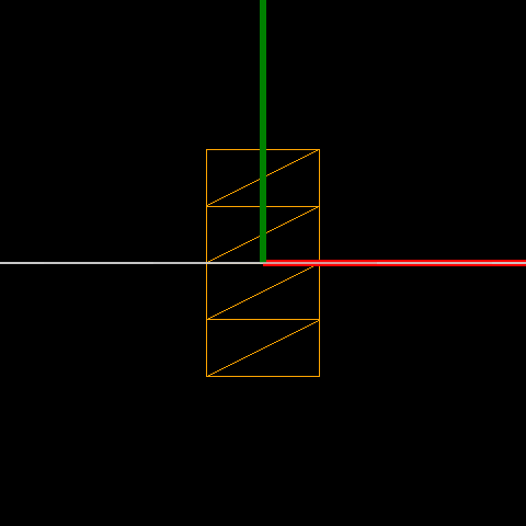
The two Joints are connected in a Skeleton. We will rotate joint1 45 degrees around the z-axis. The images below show how the joints are placed in the geometry and how the initial skeleton is oriented.
| Joints in the geometry | Initial skeleton |
|---|---|
|
|
Placing models using inverseBindPoses
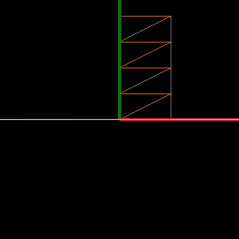
Once a model has a valid skeleton, it is necessary to define the initial pose of the skeleton. This defines the baseline for the skeletal animation: moving a joint from its initial position causes the model's vertexes to move according to the joints and weights tables. The geometry of each node is specified in a peculiar way: Model.inverseBindPoses is set to the inverse of the matrix that would transform the joint to its initial position. In order to move it to the center, we will simply set the same transform for both joints: a matrix that translates -0.5 along the x-axis and -1.0 along the y-axis.
| QML code | Initial position | Result |
|---|---|---|
inverseBindPoses: [ Qt.matrix4x4(1, 0, 0, -0.5, 0, 1, 0, -1, 0, 0, 1, 0, 0, 0, 0, 1), Qt.matrix4x4(1, 0, 0, -0.5, 0, 1, 0, -1, 0, 0, 1, 0, 0, 0, 0, 1) ] |
|
|
Animate with Joint nodes
Now that we have prepared a skinned object, we can animate it by changing the Joints' properties, specifically eulerRotation.
Timeline {
    id: timeline0
    startFrame: 0
    endFrame: 1000
    currentFrame: 0
    enabled: true
    animations: [
        TimelineAnimation {
            duration: 5000
            from: 0
            to: 1000
            running: true
        }
    ]

    KeyframeGroup {
        target: joint1
        property: "eulerRotation.z"

        Keyframe {
            frame: 0
            value: 0
        }
        Keyframe {
            frame: 250
            value: 90
        }
        Keyframe {
            frame: 750
            value: -90
        }
        Keyframe {
            frame: 1000
            value: 0
        }
    }
}
Files:
© 2024 The Qt Company Ltd. Documentation contributions included herein are the copyrights of their respective owners. The documentation provided herein is licensed under the terms of the GNU Free Documentation License version 1.3 as published by the Free Software Foundation. Qt and respective logos are trademarks of The Qt Company Ltd. in Finland and/or other countries worldwide. All other trademarks are property of their respective owners.
