Adding Action Areas and Transitions
Action areas are clickable areas that initiate transitions between flow items or create connections to any signal from any component in a flow item. For example, you could connect an action to the onPressed signal of a button in your flow item to determine what should happen when users press the button.
Select the type of the mouse or touch input to use for triggering events, such as click, double-click, flick, pinch, or long press.
Typically, a flow item is connected to several other flow items in the flow with two-way connections. To avoid clutter, set an action area as go back instead of adding explicit transition lines to and from every potentially connected flow item. When the Go back option is enabled, the transition will always take the user back to the previous flow item.
You can specify the appearance of each action area or transition line, including the color, line thickness, dotted or solid lines, and even the curve of the transition lines. You can change some of these properties globally, as instructed in Flow View Properties.
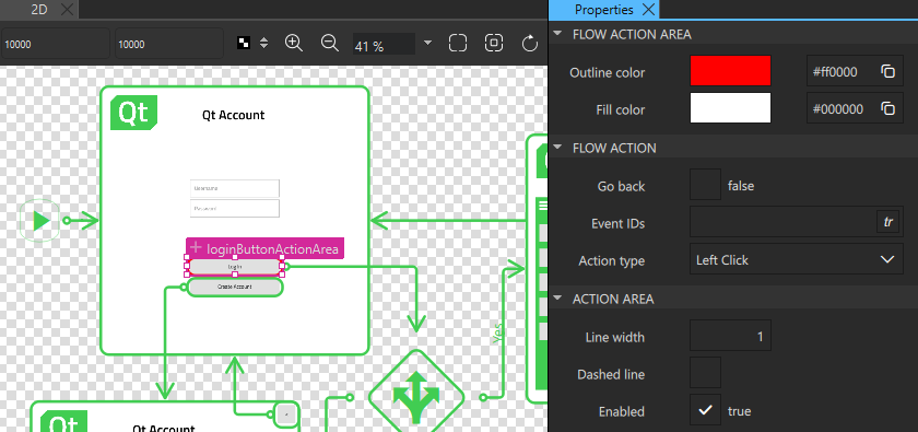
To create action areas:
- Select the flow item in the 2D view, then right-click it, and select Flow > Create Flow Action in the context menu.
- Drag the action area to the UI control that you want to connect to the other flow item. For example, to a button that opens another flow item when clicked.
- Double-click the action area and drag the transition line to the flow item you want to connect to.
- In Properties, modify the properties of the action area and transition line.
To preview the flow, select the Live Preview button on the top toolbar or press Alt + P.
Common Properties
Specify basic properties for Flow Action Area and Flow Transition components in the Component, Geometry - 2D, and Visibility sections in the Properties view.
Use anchors in the Layout tab to position the component.
Manage the more advanced properties of components in the Advanced section.
Flow Action Area Properties
Use the color picker in the Flow Action Area section to set line and fill color.
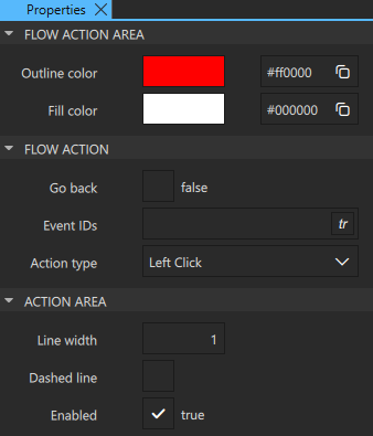
Specify additional properties for action areas in the Flow Action and Action Area sections:
- Select the Go back checkbox to specify that the transition will always take the user back to the previous flow item.
- In the Event IDs field, specify the IDs of the events to connect to, such as mouse, touch or keyboard events.
- In the Action type field, select the type of the mouse or touch input to use for triggering events.
- In the Line width field, set the width of the action area outline.
- Select the Dashed line checkbox to draw a dashed action area outline.
- Select the Enabled checkbox to enable interaction with the action area during preview.
Flow Transition Properties
Specify additional properties for transitions between flow items in the Transition section:
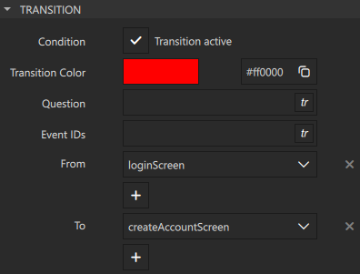
- Select the Condition checkbox to activate the transition. Select
 to bind a condition to the transition.
 - In the Question field, enter the text that will appear next to the transition line. If the transition represents the connection to a Flow Decision component, the text will also be visible in the selection dialog that opens when the condition is triggered.
- In the Event IDs field, specify the IDs of the events to connect to, such as mouse, touch or keyboard events.
- In the From and To fields, select the flow item where the transition starts and the one where it ends.
Specify the following properties to change the appearance of transition lines in the 2D view:
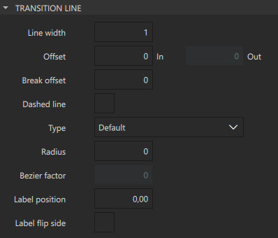
- In the Line width field, set the width of the transition line.
- In the Offset and Break offset fields, set the start point (Out) or end point (In) of a transition line or a break to the specified offset. This enables you to move them up and down or left and right.
- Select the Dashed line checkbox to draw a dashed line.
- In the Type field, select Bezier to draw transition lines as bezier curves.
- In the Radius field, specify the corner radius for default curves.
- In the Bezier factor field, specify the factor that modifies the positions of the control points used for a bezier curve.
- In the Label position field, set the position of the value of the Question field in respect to the transition start point.
- Select the Label flip side checkbox to move the Question value to the opposite side of the transition line.
Connecting and Releasing Signals
To connect components to signals, export the components first as aliases in Navigator. To create and release connections, select Open Signal Dialog in the context menu. The Signal List dialog displays the signals for all components.
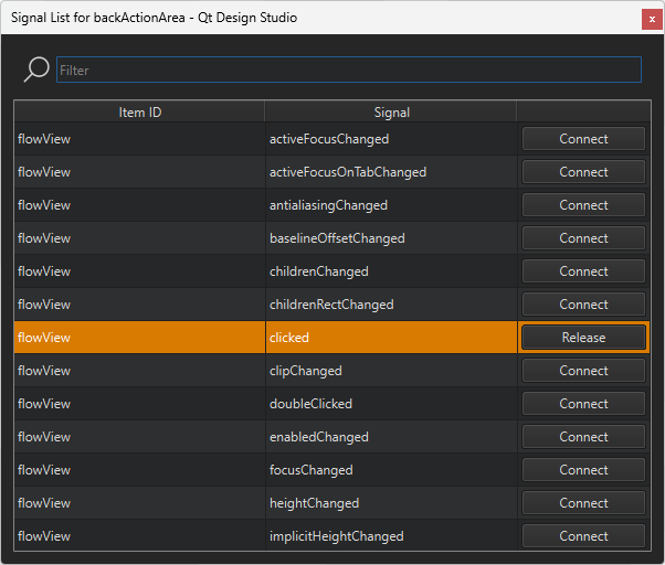
To connect a component to a signal, select Connect next to one in the list. To release a connected signal, select Release.
Available under certain Qt licenses.
Find out more.
