C
Develop the Application Backend (Traveo II)
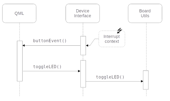
This topic guides you through the steps to create and build the application's backend using GHS MULTI IDE. The backend enables the application's UI to communicate with the platform and get the required information from the hardware. In this case, the device interface gets the status of the on-board user button. The following diagram describes the interaction between the two components:
Develop the C++ backend
The following instructions guide you through the process of developing the C++ backend for your application:
- Create a new file named
main.cppin any directory. The directory will be referred to as BACKEND_DIR:#include "YourProject.h" #include <qul/application.h> #include <qul/qul.h> int main() { Qul::initHardware(); Qul::initPlatform(); Qul::Application app; static YourProject item; app.setRootItem(&item); app.exec(); return 0; }
This file has the default entrypoint for the application. You will extend this entrypoint later with extra configuration steps to use the LED and user button. Refer to the entry point to Qt Quick Ultralite applications documentation for more information. Make sure to use the same project name (YourProject) that you chose in the earlier chapter.
- Create new C++ source and header files and name them
deviceinterface.cppanddeviceinterface.hrespectively. Save these files in the BACKEND_DIR directory that you just created. - Replace the contents of
deviceinterface.hwith the following:#ifndef DEVICEINTERFACE_H #define DEVICEINTERFACE_H #include <qul/signal.h> #include <qul/singleton.h> #include <qul/eventqueue.h> typedef int HWButtonEvent; class DeviceInterface : public Qul::Singleton<DeviceInterface>, public Qul::EventQueue<HWButtonEvent> { public: Qul::Signal<void(int button)> buttonEvent; void onEvent(const HWButtonEvent &inputEvent); void toggleLED(); }; #endif //DEVICEINTERFACE_H
The header declares the
DeviceInterfaceclass, which inherits from Qul::Singleton and Qul::EventQueue. It also declares thebuttonEventSignal and theHWButtonEventevent type. This allows the Singleton instance to be globally available. It provides an interface between C++ and QML, to emit the changed signal on receiving theHWButtonEventinput event. For more information, refer to Defining Singletons in QML and Transferring data from Interrupt Handlers to QML. - Similarly, replace the contents of
deviceinterface.cppwith the following:#include "deviceinterface.h" #include "boardutils.h" #include <platforminterface/log.h> extern "C" void DeviceInterface_handleButtonEvent() { DeviceInterface::instance().postEventFromInterrupt(0); } void DeviceInterface::onEvent(const HWButtonEvent &inputEvent) { buttonEvent(inputEvent); } void DeviceInterface::toggleLED() { Qul::PlatformInterface::log("Toggling LED\n"); BoardUtils_toggleLED(); }
- Create new C source and header files and name them
boardutils.candboardutils.hrespectively. Save these files in the BACKEND_DIR directory. - Replace the code in
boardutils.hwith the following:#ifndef BOARDUTILS_H #define BOARDUTILS_H #ifdef __cplusplus extern "C" { #endif void BoardUtils_configure(); void BoardUtils_toggleLED(); #ifdef __cplusplus } #endif #endif //BOARDUTILS_H
- Add the Traveo II specific implementation of
BoardUtils_configure()andBoardUtils_toggleLED()toboardutils.c:#include "boardutils.h" #include <stdint.h> #include <cy_project.h> #define USER_LED1_PORT CY_USER_LED1_PORT #define USER_LED1_PIN CY_USER_LED1_PIN #define USER_LED1_PIN_MUX CY_USER_LED1_PIN_MUX #define USER_BUTTON1_PORT CY_USER_BUTTON_WAKE_PORT #define USER_BUTTON1_PIN CY_USER_BUTTON_WAKE_PIN #define USER_BUTTON1_PIN_MUX CY_USER_BUTTON_WAKE_PIN_MUX #define USER_BUTTON1_IRQN CY_USER_BUTTON_WAKE_IRQN extern void DeviceInterface_handleButtonEvent(); void ButtonInterruptHandler(void) { uint32_t interruptStatus = Cy_GPIO_GetInterruptStatusMasked(USER_BUTTON1_PORT, USER_BUTTON1_PIN); if (interruptStatus) { DeviceInterface_handleButtonEvent(); Cy_GPIO_ClearInterrupt(USER_BUTTON1_PORT, USER_BUTTON1_PIN); } } void BoardUtils_configure() { // GPIO configuration for LED cy_stc_gpio_pin_config_t user_led_port_pin_cfg = { .outVal = 0x00, .driveMode = CY_GPIO_DM_STRONG_IN_OFF, .hsiom = USER_LED1_PIN_MUX, .intEdge = 0, .intMask = 0, .vtrip = 0, .slewRate = 0, .driveSel = 0, .vregEn = 0, .ibufMode = 0, .vtripSel = 0, .vrefSel = 0, .vohSel = 0, }; Cy_GPIO_Pin_Init(USER_LED1_PORT, USER_LED1_PIN, &user_led_port_pin_cfg); // GPIO configuration for button static cy_stc_gpio_pin_config_t user_button1_port_pin_cfg = { .outVal = 0x00, .driveMode = CY_GPIO_DM_HIGHZ, .hsiom = USER_BUTTON1_PIN_MUX, .intEdge = CY_GPIO_INTR_FALLING, .intMask = 1, .vtrip = 0, .slewRate = 0, .driveSel = 0, .vregEn = 0, .ibufMode = 0, .vtripSel = 0, .vrefSel = 0, .vohSel = 0, }; Cy_GPIO_Pin_Init(USER_BUTTON1_PORT, USER_BUTTON1_PIN, &user_button1_port_pin_cfg); // IRQ configuration for button cy_stc_sysint_irq_t irq_cfg = { .sysIntSrc = USER_BUTTON1_IRQN, .intIdx = CPUIntIdx2_IRQn, .isEnabled = true, }; Cy_SysInt_InitIRQ(&irq_cfg); Cy_SysInt_SetSystemIrqVector(irq_cfg.sysIntSrc, ButtonInterruptHandler); NVIC_SetPriority(CPUIntIdx2_IRQn, 3); NVIC_ClearPendingIRQ(CPUIntIdx2_IRQn); NVIC_EnableIRQ(CPUIntIdx2_IRQn); } void BoardUtils_toggleLED() { Cy_GPIO_Inv(USER_LED1_PORT, USER_LED1_PIN); }
The configure function initializes the LED and button pins. It then registers
ButtonInterruptHandler()as the interrupt request handler for the user button events using the GPIO and IRQ APIs from the Traveo II Graphics Driver. - To properly configure the Traveo II LED and button, change
main.cppto include theboardutils.hheader and to callBoardUtils_configure()after the normal platform initialization:#include "boardutils.h" ... int main() { Qul::initHardware(); Qul::initPlatform(); BoardUtils_configure(); ... }
Integrate UI and backend in Design Studio
Use the DeviceInterface Singleton object from Design Studio, to access the low-level backend functions that you implemented in the earlier section.
- Open your project in Design Studio and select the Connections pane.
- Click twice on + in the Connections tab to add two new connections.
- In the first connection, set Target to
statusRect, Signal Handler toonPressedChanged, and Action toDeviceInterface.toggleLED(). - In the second connection, set Target to
DeviceInterface, Signal Handler toonButtonEvent, and Action tostatusRect.pressed = !statusRect.pressed.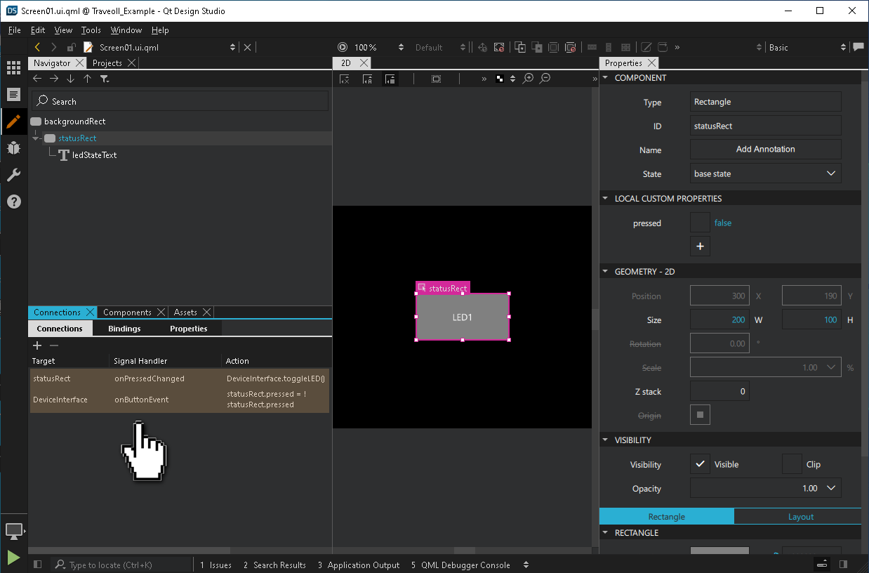
Now on press of the button, the event propagates to the QML context, which changes the
statusRect.pressedproperty. This results in changing the color of the UI item. In response to thestatusRect.pressedproperty change, theDeviceInterface.toggleLED()method toggles the LED. - Use a text editor to change
yourproject.qmlprojectto generate the necessary C++/QML interfaces needed for the singleton object:InterfaceFiles { files: ["C:/path/to/BACKEND_DIR/deviceinterface.h"] }Change the BACKEND_DIR path to the directory containing the
deviceinterface.hfile.For more information, refer to QmlProject InterfaceFiles.
Export application and platform sources
This section provides you step-by-step instructions to create a GHS MULTI IDE project, and integrate application and platform sources exported by the Qt for MCUs tools.
Note: If you are using Traveo II 6M, replace tviic2d4m-baremetal with tviic2d6m-baremetal in the following steps.
- Create a batch script with the following commands, which calls the
qmlprojectexporterto generate a GHS Multi IDE projectset QUL_ROOT=C:\path\to\QtMCUs\dev set QMLPROJECT_FILE=C:\path\to\YourProject.qmlproject set BOARDDEFAULTS=%QUL_ROOT%\platform\boards\cypress\tviic2d4m-baremetal\cmake\BoardDefaults_32bpp.qmlprojectconfig set GRAPHICS_DRIVER_DIR=C:\path\to\TVII-GraphicsDriver-V1.2.1 set PROJECT_DIR=C:\path\to\PROJECT_DIR %QUL_ROOT%\bin\qmlprojectexporter.exe %QMLPROJECT_FILE% --platform=tviic2d4m-baremetal --toolchain=ghs-arm --boarddefaults=%BOARDDEFAULTS% --outdir=%PROJECT_DIR% --project-type=ghs --include-ide-generated-hw-code --board-sdk=%GRAPHICS_DRIVER_DIR%
Note: Use the
v2e1.0graphics driver fortviic2d6m-baremetal.Before running the script, make sure that the following variables are set:
GRAPHICS_DRIVER_DIRto the Traveo II Graphics Driver install path,QUL_ROOTandQMLPROJECT_FILE.PROJECT_DIRto the output directory where you want to place the GHS project files.
Now, run the script from the command prompt to generate the following:
- C++ sources generated from QML in
%PROJECT_DIR%/QtMCUs/generated - The exported platform sources in
%PROJECT_DIR%/QtMCUs/platform - A top-level project file with subproject files in
%PROJECT_DIR%/GHS.
The generated GHS project includes the following:
%PROJECT_DIR%\GHS\project.gpj: the top-level project file%PROJECT_DIR%\GHS\prj\program.gpj: program compile definitions, include directories, compiler and linker options%PROJECT_DIR%\GHS\prj\drivers.gpj: list of TVII Graphics Driver sources%PROJECT_DIR%\GHS\prj\QtMCUs\qul_platform.gpj: list of Traveo II 4M platform sources%PROJECT_DIR%\GHS\prj\QtMCUs\qul_app.gpj: list of generated sources from the main.qmlprojectfile%PROJECT_DIR%\GHS\prj\QtMCUs\qul_module_<ModuleName>.gpj: One subproject for each module, including the sources generated for the corresponding module.qmlprojectfile.%PROJECT_DIR%\GHS\prj\application.gpj: a convenience empty subproject for the application which you will edit in the next section
For more information, refer to Exporting a Qt for MCUs project with platform sources.
Build application in GHS MULTI IDE
The following instructions guide you through the GHS project adaptation steps needed to build the application:
- Launch the GHS MULTI IDE Project Manager (
multi.exe) - Select File > Open Project and select the top-level
project.gpjfile exported in the earlier section. - Right-click
application.gpjand select Edit. Replace its contents with the following to add the source files from BACKEND_DIR:#!gbuild macro APPLICATION_EXPORT_DIR=C:/path/to/PROJECT_DIR/QtMCUs/generated macro BACKEND_DIR=C:/path/to/BACKEND_DIR [Subproject] -DQUL_STD_STRING_SUPPORT -I${APPLICATION_EXPORT_DIR} # ----- backend ----- ${BACKEND_DIR}/main.cpp ${BACKEND_DIR}/boardutils.cpp ${BACKEND_DIR}/deviceinterface.cppMake sure to set the
APPLICATION_EXPORT_DIRmacro to the directory that has the exported UI sources, and the BACKEND_DIR macro to the directory containing the backend sources andmain.cpp.Note: Indentation is important in
.gpjproject files. Refer to the MULTI IDE documentation for more information - The application binary name is
application.elfby default. To use a different name, change-o application.elfto-o YourProject.elfin theprogram.gpjproject file. - Your application is now ready. Build your GHS MULTI project and flash it to the Traveo II board using the Infineon Auto Flash Utility to run it on the target hardware.
The following command shows how to flash the application to the board. Replace the Infineon Auto Flash Utility path if necessary. If you are using the J-Link probe instead of a MiniProg4, replace
kitprog3.cfgwithjlink.cfg. If your target board is a Traveo II 6M instead of a Traveo II 4M, replacetraveo2_c2d_4m.cfgwithtraveo2_6m.cfg:"C:\Program Files (x86)\Infineon\Auto Flash Utility 1.2\bin\openocd.exe" -s "C:\Program Files (x86)\Infineon\Auto Flash Utility 1.2\scripts" -f interface/kitprog3.cfg -c "set ENABLE_HYPERFLASH_0 1" -c "transport select swd" -f target/traveo2_c2d_4m.cfg -c "init; reset init; program C:/path/to/YourProject.elf verify; shutdown"
You will also need to flash a bootloader to the CM0+ core of the Traveo II board. First, set
QUL_ROOTto the same value as in the earlier batch scripts. Next, use the earlier Infineon Auto Flash Utility command and replace the path toYourProject.elfwith the following:- Traveo II 4M
%QUL_ROOT%/bin/bootloaders/cypress/tviic2d4m-baremetal_bootloader.elf
- Traveo II 6M
%QUL_ROOT%/bin/bootloaders/cypress/tviic2d6m-baremetal_bootloader.elf
- Traveo II 4M
Making changes to the UI
If you make any changes to the UI parts of your application, export the UI sources again using qmlprojectexporter.
Automatically updating an existing project with new UI sources is not currently implemented. To apply changes made to the UI, you have to update the project files manually.
- Use
qmlprojectexporterto generate files with the following batch script:set QUL_ROOT=C:\path\to\QtMCUs\dev set QMLPROJECT_FILE=C:\path\to\YourProject.qmlproject set BOARDDEFAULTS=%QUL_ROOT%\platform\boards\cypress\tviic2d4m-baremetal\cmake\BoardDefaults_32bpp.qmlprojectconfig set PROJECT_DIR=C:\path\to\PROJECT_DIR set QMLPROJECT_DIR=%PROJECT_DIR%\QtMCUs\generated %QUL_ROOT%\bin\qmlprojectexporter.exe %QMLPROJECT_FILE% --platform=tviic2d4m-baremetal --toolchain=ghs-arm --boarddefaults=%BOARDDEFAULTS% --outdir=%QMLPROJECT_DIR%
- Update the existing project files with the new sources. There is one subproject for the main
.qmlprojectfile, calledqul_app.gpjand one subproject for each module, with the naming schemequl_module_<QmlProjectName>.gpj.You can find a list of generated source files in
%APPLICATION_EXPORT_DIR%\config\<QmlProjectName>.1.compiler_outputs.txt, whereQmlProjectNamecorresponds to the name of a QmlProject. Add the C++ source files from eachcompiler_outputs.txtfile to its respective subproject in GHS MULTI IDE. - If you have added new modules since the initial generation, add them manually as a subproject. To do this, right-click application.gpj and select Add Item into application.gpj. Select Subproject from the popup, and place the new file in
%PROJECT_DIR%\GHS\prj\QtMCUswith the namequl_module_<ModuleName>.gpj.Find the list of generated sources in the
compiler_outputs.txtfile for this module, and add them to the subproject you just created. - Update linked libraries as they might have changed since the last update. You will find the list of required libraries in the
<QmlProjectName>.1.libraries.txtfile(s) in the%APPLICATION_EXPORT_DIR\configdirectory. For example, they might list the following libraries:- Qul::MonotypeUnicode
- Qul::MonotypeUnicodeEngineShaperDisabled
- Qul::PNGDecoderNull
Identify the corresponding libraries for your build type and platform in the
${QUL_DIR}/libfolder and add them toprogram.gpjwith the-ldirective if they are not already listed. For the example libraries listed above, these are the corresponding library files to link against inprogram.gpj:-l${QUL_DIR}/lib/libQulMonotypeUnicode_tviic2d4m-baremetal_Windows_ghs-arm_MinSizeRel.a-l${QUL_DIR}/lib/libQulMonotypeUnicodeEngineShaperDisabled_tviic2d4m-baremetal_Windows_ghs-arm_MinSizeRel.a-l${QUL_DIR}/lib/libQulPNGDecoderNull_tviic2d4m-baremetal_Windows_ghs-arm_MinSizeRel.a
Note: if any of the
libraries.txtfiles listQul::PNGDecoderLodePNG, you must NOT link againstQul::PNGDecoderNull.
Available under certain Qt licenses.
Find out more.
