Qt 3D Overview
Qt 3D provides C++ and QML APIs to incorporate 3D content into Qt applications.
Qt 3D provides a fully configurable renderer that enables developers to quickly implement any rendering pipeline that they need. Further, Qt 3D provides a generic framework for near-realtime simulations beyond rendering.
Qt 3D is cleanly separated into a core and any number of aspects that can implement any functionality they wish. The aspects interact with components and entities to provide some slice of functionality. Examples of aspects include physics, audio, collision, artificial intelligence (AI), and path finding.
Basic 3D Features
Qt 3D is a 3D framework that enables the drawing of 3D shapes and moving them around, as well as moving the camera. It supports the following basic features:
Materials
Qt 3D has a robust and very flexible material system that allows multiple levels of customization. It caters for different rendering approaches on different platforms or OpenGL versions, enables multiple rendering passes with different state sets, provides mechanisms for overriding of parameters at different levels, and allows easy switching of shaders. All this from C++ or using QML property bindings.
The properties of a Material type can easily be mapped through to uniform variables in a GLSL shader program that is itself specified in the referenced effect property.
For examples of using materials, see the following examples:
Qt 3D: Simple Custom Material QML Example
Qt 3D: PBR Materials QML Example
Shaders
Qt 3D supports all of the OpenGL programmable rendering pipeline stages: vertex, tessellation control, tessellation evaluation, geometry, and fragment shaders. Compute shaders are planned for a future release.
For examples of using shaders, see the Qt 3D: Wireframe QML Example .
Shadow Mapping
Shadows are not directly supported by OpenGL, but there are countless techniques that can be employed to generate them. Shadow mapping is simple to use for generating good-looking shadows, while having a very small performance cost.
Shadow mapping is typically implemented using a two pass rendering. In the first pass, the shadow information is generated. In the second pass, the scene is generated using a particular rendering technique, while at the same time using the information gathered in the first pass to draw the shadows.
The idea behind shadow mapping is that only the closest fragments to the light are lit. Fragments behind other fragments are occluded, and therefore in shadow.
Therefore, in the first pass, the scene is drawn from the point of view of the light. The information that is stored is simply the distance of the closest fragment in this light space. In OpenGL terms, this corresponds to having a Framebuffer Object, or FBO, with a depth texture attached to it. In fact, the distance from the eye is the definition of the depth, and the default depth testing done by OpenGL will actually store only the depth for the closest fragment.
A color texture attachment is not even needed, because there is no need to shade fragments, only to calculate their depth.
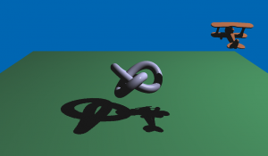
The following image displays a scene with a self-shadowed plane and trefoil knot:
The following image shows an exaggerated shadow map texture of the scene:

The image indicates the depth stored when rendering the scene from the light point of view. Darker colors represent a shallow depth (that is, closer to the camera). In this scene, the light is placed somewhere above the objects in the scene, on the right side with respect to the main camera (compare this with the first screenshot). This matches with the fact that the toy plane is closer to the camera than the other objects.
Once the shadow map has been generated, the second rendering pass is done. In this second pass, rendering is done using the normal scene’s camera. Any effect can be used here, such as Phong shading. It is important that the shadow map algorithm is applied in the fragment shader. That is, the fragment that is closest to the light is drawn lit, whereas the other fragments are drawn in shadow.
The shadow map generated in the first pass provides the necessary information about the distance of fragments to light. It then suffices to remap the fragment in light space, thereby calculating its depth from the light point of view, as well as where its coordinates are on the shadow map texture. The shadow map texture can then be sampled at the given coordinates and the fragment’s depth can be compared with the result of the sampling. If the fragment is further away, then it is in shadow; otherwise it is lit.
Instanced Rendering
Instancing is a way of getting the GPU to draw many copies (instances) of a base object that varies in some way for each copy. Often, in position, orientation, color, material properties, scale, and so on. Qt 3D provides an API similar to the Qt Quick Repeater element. In this case, the delegate is the base object and the model provides the per-instance data. So whereas an entity with a Mesh component attached eventually gets transformed into a call to glDrawElements, an entity with a instanced component will be translated into a call to glDrawElementsInstanced.
Instanced rendering is planned for a future release.
Uniform Buffer Objects
A Uniform Buffer Object (UBO) can be bound to OpenGL shader programs to make large amounts of data readily available. Typical use cases for UBOs are for sets of material or lighting parameters.
Useful Tips
Some very useful programming tips for 3D rendering can be found on this page: Qt 3D Render Pro Tips .
Configurable Renderer
To combine support for both C++ and QML APIs with having a fully configurable renderer, the concept of a framegraph was introduced. While a scenegraph is a data-driven description of what to render, a framegraph is a data-driven description of how to render it.
A framegraph enables developers to choose between a simple forward renderer, including a z-fill pass, or using a deferred renderer for example. It also gives them control over when to render any transparent objects, and so on. Since this is all configured purely from data, it is very easy to modify even dynamically at runtime without touching any C++ code. It is possible to extend Qt 3D by creating your own framegraphs that implement custom rendering algorithms.
3D Extensions
Beyond the essentials of displaying 3D content on the screen, Qt 3D is extensible and flexible enough to act as a host for the following types of extensions related to the 3D objects:
Physics simulation
Collision detection
3D positional audio
Rigid body, skeletal, and morph target animation
Path finding and other AI
Picking
Particles
Object spawning
Performance
Qt 3D is designed to perform well and scale up with the number of available CPU cores, because modern hardware improves performance by increasing the numbers of cores rather than base clock speed. Using multiple cores works well, because many tasks are independent of each other. For example, the operations performed by a path finding module do not overlap strongly with the tasks performed by a renderer, except maybe when rendering debug information or statistics.
Qt 3D Architecture
The main use cases of Qt 3D are simulating objects in near-realtime and rendering the state of those objects onto the screen. The Space Invaders example contains the following objects:
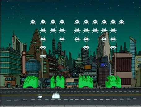
The player’s ground cannon
The ground
The defensive blocks
The enemy space invader ships
The enemy boss flying saucer
The bullets shot by the enemies and the player
In a traditional C++ design, these types of object would typically be implemented as classes arranged in some kind of inheritance tree. Various branches in the inheritance tree might add additional functionality to the root class for features such as:
Accepts user input
Plays a sound
Is animated
Collides with other objects
Is drawn on screen
The types in the Space Invaders example can be classified against these features. However, designing an elegant inheritance tree for even such a simple example is not easy.
This approach and other variations on inheritance present a number of problems:
Deep and wide inheritance hierarchies are difficult to understand, maintain and extend.
The inheritance taxonomy is set in stone at compile time.
Each level in the class inheritance tree can only classify upon a single criteria or axis.
Shared functionality tends to bubble up the class hierarchy over time.
It is impossible to predict what the developers will want to do.
Extending deep and wide inheritance trees usually requires understanding, and agreeing with, the taxonomy used by the original author. Therefore, Qt 3D places focus on aggregation instead of inheritance as the means of imparting functionality onto an instance of an object. Specifically, Qt 3D implements an Entity Component System (ECS).
Using an ECS
In an ECS, an entity represents a simulated object, but by itself it is devoid of any specific behavior or characteristics. Additional behavior can be grafted onto an entity by having the entity aggregate one or more components. Each component is a vertical slice of behavior of an object type.
In the Space Invaders example, the ground is an entity with an attached component that tells the system that the entity needs rendering and what kind of rendering it needs. An enemy space invader ship is another entity with attached components that cause the ship to be rendered, but also enable it to emit sounds, be collided with, be animated, and be controlled by a simple AI.
The player’s ground cannon entity has mostly similar components to the enemy space invader ship, except that it does not have the AI component. In its place, the cannon has an input component to enable the player to move it around and to fire bullets.
ECS Backend
The backend of Qt 3D implements the system part of the ECS paradigm in the form of aspects. An aspect implements the particular vertical slice of the functionality provided to entities by a combination of one or more of their aggregated components.
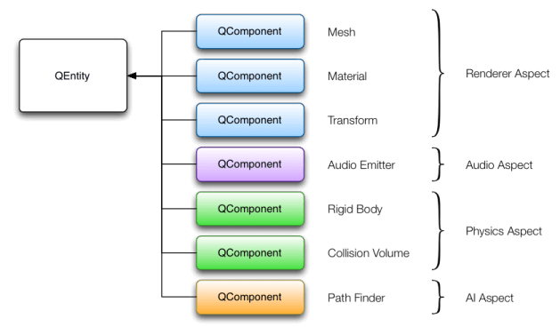
For example, the renderer aspect looks for entities that have mesh, material, and optionally transformation components. If the renderer aspect finds such an entity, it knows how to take that data and draw something nice from it. If an entity does not have those components, the renderer aspect ignores it.
Qt 3D builds custom entities by aggregating components that provide additional capabilities. The Qt 3D engine uses aspects to process and update entities with specific components.
For example, a physics aspect looks for entities that have some kind of collision volume component and another component that specifies other properties needed by such simulations like mass, coefficient of friction, and so on. An entity that emits sound has a component that specifies it is a sound emitter, as well as specifying when and which sounds to play.
Because ECS uses aggregation rather than inheritance, it is possible to dynamically change how an object behaves at runtime simply by adding or removing components.
For example, to enable a player to suddenly run through walls after a power-up, that entity’s collision volume component can be removed temporarily, until the power-up times out. There is no need to create a special one-off subclass for PlayerWhoRunsThroughWalls.
Qt 3D ECS Implementation
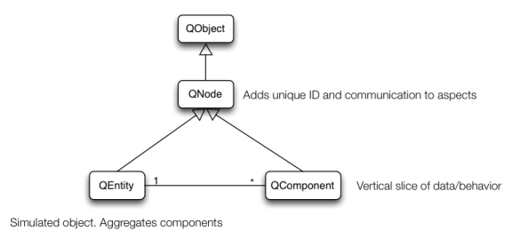
Qt 3D implements ECS as a simple class hierarchy. The Qt 3D base class is QNode , which is a subclass of QObject. QNode adds to QObject the ability to automatically communicate property changes to aspects and an ID that is unique throughout an application. The aspects exist in additional threads and QNode simplifies the data transfer between the user-facing objects and the aspects.
Typically, subclasses of QNode provide additional supporting data that is referenced by components. For example, the QShaderProgram class specifies the GLSL code to be used when rendering a set of entities.
Components in Qt 3D are implemented by subclassing QComponent and adding the data necessary for the corresponding aspect to do its work. For example, the mesh component is used by the renderer aspect to retrieve the per-vertex data that should be sent down the OpenGL pipeline.
Finally, QEntity is simply an object that can aggregate zero or more QComponent instances.
Extending Qt 3D
Adding functionality to Qt 3D, either as part of Qt or specific to your own applications to benefit from the multi-threaded back-end consists of the following tasks:
Identify and implement any necessary components and supporting data.
Register the components with the QML engine (only if you use the QML API).
Subclass QAbstractAspect and implement the subsystem functionality.
Qt 3D Task-Based Engine
In Qt 3D, aspects are asked in each frame for a set of tasks to execute along with the dependencies between them. The tasks are distributed across all the configured cores by a scheduler to improve performance.
Qt 3D’s Aspects
By default, Qt 3D provides the Qt3DRender and Qt3DInput aspects. The components and other supporting classes provided by these aspects are discussed in the documentation for those modules.
Additional aspects providing more capabilities will be added in future versions of Qt 3D.