Create UML-style models
Use wizards to create UML-style models and scratch models.
To create models and edit them in the model editor:
- Go to File > New File > Modeling > Model, and then select Choose.
The model file opens in the model editor.
- Drag model elements to the editor and select them to specify properties for them:
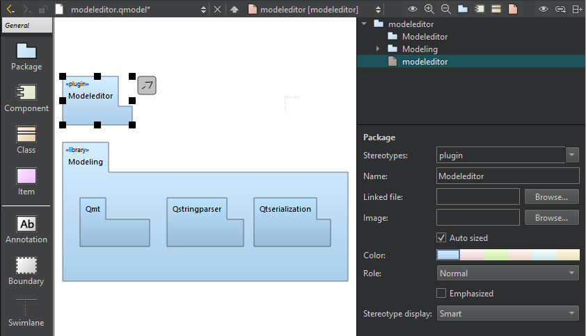
A package diagram in the model editor.
- In Stereotypes, enter the stereotype to apply to the element or select a predefined stereotype from the list.
- In Name, give a name to the element.
- In Linked file, select a file to create a link to it from the element name.
- In Image, select an image to use as a custom icon for the element.
- Select Auto sized to reset the element to its default size after you changed the element size by dragging its borders.
- In Color, select the color of the element.
- In Role, select a role to make the model element color lighter, darker, or softer. You can also remove color and draw the element outline or flatten the element by removing gradients.
- Select Emphasized to draw the model element with a thicker line.
- In Stereotype display, select:
- Smart to display the stereotype as a Label, a Decoration, or an Icon, depending on the properties of the element. For example, if a class has the stereotype interface, it is displayed as an icon until it becomes displayed members, after which it is displayed as a decoration.
- None to suppress the displaying of the stereotype.
- Label to display the stereotype as a line of text using the standard form above the element name even if the stereotype defines a custom icon.
- Decoration to show the standard form of the element with the stereotype as a small icon placed top right if the stereotype defines a custom icon.
- Icon to display the element using the custom icon.
- To create a relation between two elements, select the arrow icon next to an element and drag it to the end point of the relation.
- Select the relation to specify settings for it, according to its type: inheritance, association, or dependency. You can specify the following settings for dependency relations, which are available for all element types:
- In Stereotypes, select the stereotype to apply to the relation.
- In Name, give a name to the relation.
- In Direction, change the direction of the connection or make it bidirectional.
- To move the end of a relation to a different element, drag the end point over another element that accepts relations of that type. For example, only classes accept inheritances and associations.
- To create sampling points that divide a relation into two connected lines, select a relation and press Shift and click on the relation line.
If possible, the end point of a relation is moved automatically to draw the line to the next sampling point either vertically or horizontally.
- To remove a sampling point, press Ctrl and click the sampling point.
- To group elements, drag a Boundary element to the editor and resize it to enclose the elements in the group.
Create scratch models
Use a scratch model to quickly put a temporary diagram together. The wizard creates the model file in a temporary folder without any input from you. Therefore, you can assign a keyboard shortcut to the wizard and use it to create and open models with empty diagrams.
To create a scratch model, go to File > New File > Modeling > Scratch Model, and then select Choose.
See also How To: Create Models and Diagrams and Model Editor.
© 2024 The Qt Company Ltd. Documentation contributions included herein are the copyrights of their respective owners. The documentation provided herein is licensed under the terms of the GNU Free Documentation License version 1.3 as published by the Free Software Foundation. Qt and respective logos are trademarks of The Qt Company Ltd in Finland and/or other countries worldwide. All other trademarks are property of their respective owners.
