C
EK-RA6M3G Kit
This topic provides board-specific information about Renesas' EK-RA6M3G.
Board features
- R7FA6M3AH3CFC MCU featuring ARM Cortex-M4, 2 MB Flash, 640 KB RAM
- 4.3” 480x272 LCD Touch Display
- 32 MB External QSPI Flash
Supported color depths
The reference port for this board supports 16bpp color depth. The board also supports 24bpp and 32bpp, but they are not implemented in the reference port. See QUL_COLOR_DEPTH and Color depth for more information.
Configure the operating mode
Select an operating mode for the MCU using the J16 jumper on the board, depending on the software used with the MCU.
| MCU Boot mode | Jumper J16 | USB port for the connection |
|---|---|---|
| Normal/Single-Chip mode | Open | J10 |
| SCI/USB Boot mode | Closed | J11 |
See Renesas RA6M3 Group - User’s Manual: Hardware for the details.
Flashing the firmware
Select an appropriate boot mode for the MCU before flashing the firmware using one of the tools listed below.
| Software | MCU Boot mode |
|---|---|
| Renesas e2 studio | Normal/Single-Chip mode |
| SEGGER J-Link/J-Flash (Lite) | Normal/Single-Chip mode |
Prebuilt demos and examples
The Qt for MCUs package for EK-RA6M3G board comes with a prebuilt thermo demo binary. You can find it in the demos_images directory.
Building applications with prebuilt Qt Quick Ultralite libraries
- Open the CMake project file for the example you want to build.
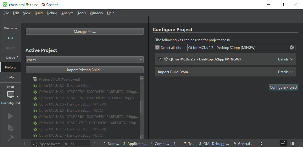
- In the Configure Project window:
- Select the kit you created earlier. For example, Qt for MCUs 2.11.0 - Desktop 32bpp.
- Select Configure Project.
Once the project is configured, select Run or press Ctrl+r on your keyboard to build and flash the binary to the target.
Reading debug messages
By default, log data is redirected to UART on the Serial Communications Interface channel 0 (SCI0).
| Board pin number | Board pin type | TTL-232-USB cable pin |
|---|---|---|
GND | Ground | GND |
P410 | RXD0 | TXD |
P411 | TXD0 | RXD |
Port settings
| Setting | Value |
|---|---|
| Bits per second | 115200 |
| Data bits | 8 |
| Parity | None |
| Stop bits | 1 |
| Flow control | None |
Debugging
Renesas e2 studio
Renesas e2 studio lets you debug a project using a custom configuration.
- Open Run from the top menu
- Select Debug Configurations...
- Select Renesas GDB Hardware Debugging
- Click Browse... from the C/C++ Application: and select .elf file to be debugged
- Click Apply and Close
- Click Launch in 'Debug' mode
SEGGER J-Link GDB Server
Use SEGGER J-Link GDB Server to create GDB server.
QUL_ROOT and QUL_TOOLS are used in the command line examples below as if they were set as environment variables. For example:
export QUL_ROOT=$HOME/Qt/QtMCUs/2.11.0
export QUL_TOOLS=$HOME/Qt/Tools/QtMCUs
set QUL_ROOT=C:\Qt\QtMCUs\2.11.0
set QUL_TOOLS=C:\Qt\Tools\QtMCUs
- Select Connection to J-Link as USB
- Select Target device as R7FA6M3AH
- Select Target interface as SWD
- Select Speed as Fixed 4000 kHz
- Click OK
GDB Server is now listening for TCP connections on the default port, 2331.
- Run
arm-none-eabi-gdbin a separate console$QUL_TOOLS/arm_gcc_12_3_1/bin/arm-none-eabi-gdb <PATH_TO>/your_app.elf
%QUL_TOOLS%\arm_gcc_12_3_1\bin\arm-none-eabi-gdb.exe <PATH_TO>\your_app.elf
- Connect to the target via the gdbserver in the
arm-none-eabi-gdbconsole usingNote: Actual TCP port used is printed out on gdbserver's console.
(gdb) target remote 127.0.0.1:2331
Notes
- Excludes demos, examples, and tests that do not fit into the flash memory or require more RAM than available on the MCU.
- Set stack region to overlap with the heap region in the default platform adaptation, to enable building tests and demos, which have different stack and heap requirements.
- Define size for the stack and heap to ensure that the Memory Protection Unit detects stack overflow and underflow.
- Image and font data are stored into the MCU's internal flash memory by default. The larger Qt Quick Ultralite demos do not fit into internal flash memory for release or debug builds. In that case, sections
QulResourceDataExtFlashandQulFontResourceDataExtFlashcan be used to move image or font data into the external flash memory. For reference, see ImageFiles.MCU.resourceStorageSection, MCU.Config.fontFilesStorageSection, and MCU.Config.glyphsStorageSection.
Default FSP Configuration in Renesas e2 studio
Note: Use the default value for the property if not specified in the table.
BSP
| Property | Value |
|---|---|
| RA Common > Main stack size (bytes) | 32768 |
| RA Common > Heap size (bytes) | 102400 |
Notes:
- The values listed earlier are relevant for initial testing only, as the stack and heap sizes are application-specific.
- On default platform adaptation, these values do not have any effect as custom implementation allows the stack region to overlap with the heap region.
- Use the
startup.candsystem.cfiles from the e2 Studio project to set the stack and heap size. You can find these system files in thera/fsp/src/bsp/cmsis/Device/RENESAS/Sourcedirectory. - Use the
script/fsp.ldlinker script generated by e2 Studio as a reference to set stack and heap regions properly.
Stacks
Add the following stacks and configure them:
Analog > ADC (r_adc)
| Property | Value |
|---|---|
| Module > General > Name | g_adc0 |
| Module > Input > Channel Scan Mask > Channel 2 | Selected |
| Pins > AN02 | P002 |
Connectivity > I2C Master (r_iic_master)
| Property | Value |
|---|---|
| Module > Name | g_i2c_touch |
| Module > Channel | 2 |
| Module > Rate | Fast-mode |
| Module > Rise Time (ns) | 120 |
| Module > Fall Time (ns) | 120 |
| Module > Duty Cycle (%) | 50 |
| Module > Slave Address | 0x38 |
| Module > Address Mode | 7-bit |
| Module > Timeout Mode | Short Mode |
| Module > Callback | touch_i2c_callback |
| Module > Interrupt Priority Level | Priority 6 |
| Pins > SDA | P511 |
| Pins > SCL | P512 |
Connectivity > UART (r_sci_uart)
| Property | Value |
|---|---|
| Module > General > Name | g_uart0 |
| Module > General > Channel | 0 |
| Module > General > Data Bits | 8bits |
| Module > General > Parity | None |
| Module > General > Stop Bits | 1bit |
| Module > Interrupts > Callback | user_uart_callback |
| Pins > TXD_MOSI | P411 |
| Pins > RXD_MISO | P410 |
Note: Set the Operation Mode to Asynchronous UART while assigning the pins for the UART. Additionally, either disable SPI0 or assign different pins to use the P410 and P411 pins for UART.
Graphics > D/AVE 2D Port Interface (r_drw)
| Property | Value |
|---|---|
| Common > Allow Indirect Mode | Enabled |
| Common > Memory Allocation | Custom |
| Module > D2 Device Handle Name | d2_handle0 |
| Module > DRW Interrupt Priority | Priority 2 |
Graphics > Graphics LCD (r_glcdc)
| Property | Value |
|---|---|
| Module > General > Name | g_display0 |
| Module > Interrupts > Callback Function | glcdc_callback |
| Module > Interrupts > Line Detect Interrupt Priority | Priority 2 |
| Module > Input > Graphics Layer 1 > General > Horizontal size | 480 |
| Module > Input > Graphics Layer 1 > General > Vertical size | 272 |
| Module > Input > Graphics Layer 1 > Framebuffer > Number of framebuffers | 1 |
| Module > Input > Graphics Layer 1 > Framebuffer > Section for framebuffer allocation | .bss |
| Module > Output > Timing > Horizontal total cycles | 525 |
| Module > Output > Timing > Horizontal active video cycles | 480 |
| Module > Output > Timing > Horizontal back porch cycles | 40 |
| Module > Output > Timing > Horizontal sync signal cycles | 1 |
| Module > Output > Timing > Horizontal sync signal polarity | Low active |
| Module > Output > Timing > Vertical total lines | 316 |
| Module > Output > Timing > Vertical active video lines | 272 |
| Module > Output > Timing > Vertical back porch lines | 8 |
| Module > Output > Timing > Vertical sync signal cycles | 1 |
| Module > Output > Timing > Vertical sync signal polarity | Low active |
| Module > Output > Timing > Data Enable Signal Polarity | High active |
| Module > Output > Timing > Sync edge | Rising edge |
| Module > Output > Format > Color format | 16bits RGB565 |
| Module > TCON > Hsync pin select | LCD_TCON0 |
| Module > TCON > Vsync pin select | LCD_TCON1 |
| Module > TCON > Panel clock division ratio | 1/32 |
Note: If you need double buffering, change Number of framebuffers to 2.
Input > External IRQ (r_icu)
| Property | Value |
|---|---|
| Module > Name | g_S1_irq0 |
| Module > Channel | 13 |
| Module > Trigger | Falling |
| Module > Digital Filtering | Enabled |
| Module > Digital Filtering Sample Clock | PCLK / 64 |
| Module > Callback | s1_irq_callback |
| Module > Pin Interrupt Priority | Priority 12 |
| Pins > IRQ13 | P009 |
Input > External IRQ (r_icu)
| Property | Value |
|---|---|
| Module > Name | g_touch_irq |
| Module > Channel | 0 |
| Module > Trigger | Falling |
| Module > Digital Filtering | Enabled |
| Module > Digital Filtering Sample Clock | PCLK / 64 |
| Module > Callback | touch_irq_cb |
| Module > Pin Interrupt Priority | Priority 5 |
| Pins > IRQ00 | P206 |
Note: Ensure that P206 is IRQ mode and its Pull up property is input pull-up.
Storage > QSPI (r_qspi)
| Property | Value |
|---|---|
| Module > General > Name | g_qspi0 |
| Module > General > Bus Timing > Minimum QSSL Deselect Cycles | 8 QSPCLK |
Timers > Timer, General PWM (r_gpt)
| Property | Value |
|---|---|
| Common > Pin Output Support | Enabled |
| Module > General > Name | g_timer_PWM |
| Module > General > Channel | 7 |
| Module > General > Mode | Saw-wave PWM |
| Module > General > Period | 10 |
| Module > General > Period Unit | Milliseconds |
| Module > Output > Duty Cycle Percent | 75 |
| Module > Output > GTIOCA Output Enabled | True |
| Module > Output > GTIOCA Stop Level | Pin Level High |
| Pins > GTIOCA | P603 |
Note: When setting the GTIOCA pin, ensure that Operation Mode of the GPT Timer is GTIOCA or GTIOCB, and pin P603 is Peripheral mode.
Known issues or limitations
- Does not support asset preloading due to limited amount of RAM and non-availability of SDRAM on the evaluation kit board.
- Uses single-buffering technique by default due to limited amount of RAM. This might result in on-screen flickering. Double-buffering can be enabled from the Renesas e2 studio Graphics LCD (
r_glcdc) stack configuration. - To prevent visual artifacts from appearing, try to reduce the use of rotated or perspective-transformed images that need to be blended using the CPU. Rebuilding the Qt Quick Ultralite core library in
Releasemight help reducing such artifacts.
Available under certain Qt licenses.
Find out more.
