C
Create an NXP MCUXpresso IDE project
This topic offers step-by-step instructions to create an NXP MCUXpresso IDE project, and integrate your application and platform sources.
You'll need the MCUXpresso SDK version 2.16.0 that includes both the MCUXpresso IDE and ARM GCC toolchains. You can either use the SDK offered by Qt Online Installer, or download the SDK by yourself. Newer versions of the MCUXpresso IDE or the board SDK might work, but have not been tested.
If you want to build the SDK yourself, install the following components:
- All toolchains (this ensures that both ARM GCC and MCUXpresso files are included)
- FreeRTOS
- VG-Lite GPU Library
Create a new project
Extract the SDK to a directory of your choice, and follow these instructions:
- Launch MCUXpresso IDE and install the downloaded SDK:
- Ensure that you can see the SDK view by selecting Window > Show View > Installed SDKs.
- Go to Installed SDKs.
- Select and hold or right-click on the view and select Import folder.... If you have the SDK as an archive, you can also choose Import archive....
- Select the folder/archive and select Open to import the SDK into the IDE.
- Create a new project for i.MX RT1170 EVKB using File > New > Create a new C/C++ Project.
- Select evkbmimxrt1170 board and select Next.
- In the next screen, select MIMXRT1176DVMAA device package. The project should have the following settings:
- Cores: cm7 core is set to Standalone Role.
- Board: Default board files
- Project Type: C++ Project
- Project Options: SDK Debug Console is set to UART. Both Copy sources and Import other files are selected.
Select also the components on the following list:
- Operating Systems
- RTOS > Core > FreeRTOS kernel
- Drivers
- Device > SDK Drivers
- anatop_ai
- clock
- common
- dcdc_soc
- elcdif
- gpio
- i2c
- iomuxc
- lcdifv2
- lpuart
- memory
- mipi_dsi
- nic301
- pmu
- pxp
- soc_mipi_csi2rx
- xip_device
- Device > SDK Drivers
- CMSIS Include
- CMSIS > CORE > CMSIS_Include_CM
- Device > CMSIS > MIMXRT1176_CMSIS
- Device > CMSIS > MIMXRT1176_system
- Utilities
- Device > SDK Drivers > lpuart_adapter
- Device > SDK Utilities
- assert
- debug_console
- serial_manager
- serial_manager_uart
- Board Components
- Board Support > SDK Drivers > xip_board
- Device > SDK Drivers
- display-hx8394
- display-rm68191
- display-rm68200
- xmcd
- Abstraction Layer
- Device > SDK Drivers
- dc-fb-common
- dc-fb-elcdif
- dc-fb-lcdifv2
- display-common
- Device > SDK Drivers
- Software Components
- Device > SDK Drivers
- display-mipi-dsi-cmd
- lists
- video-common
- Device > SDK Drivers
- Project Template
- Board Support > SDK Project Template > evkbmimxrt1170
- Other
- Device > Startup > MIMXRT1176_startup
Select Next to proceed to the next screen.
- In Advanced project settings change the following settings:
- Set Floating Point type: FPv5-D16 (Hard ABI)
- Language standard: GNU C++17 (-std=gnu++17)
Select Finish to complete the project setup.
Configure the pins and import extra SDK components
- Configure the NXP i.MX RT1170 pins using the ConfigTools > Pins option. For more information, refer to Configure NXP i.MX RT1170 pins.
- Import extra SDK components:
- Select and hold or right-click the project and select Import.
- Select File System.
- Add
<SDK_PATH>/components/gt911for the From directory field and selectfsl_gt911.h/*.cfiles. - Add
<PROJECT_NAME>/gt911for the Into folder field and select Finish. - Import the following directories (including the files and subdirectories in them) from
<SDK_PATH>/middleware/vgliteinto<PROJECT_NAME>/vglite:incVGLiteVGLiteKernel
- Import
startup_MIMXRT1176_cm7.Sfrom<SDK_PATH>/devices/MIMXRT1176/gccinto<PROJECT_NAME>/startup. Remove<PROJECT_NAME>/startup/startup_mimxrt1176_cm7.c/.cppfrom the project. - Import
heap_4.cfrom<SDK_PATH>/rtos/freertos/freertos-kernel/portable/MemManginto<PROJECT_NAME>/freertos/freertos-kernel/portable/MemMang.
Develop the application backend
- Create UI communicator struct
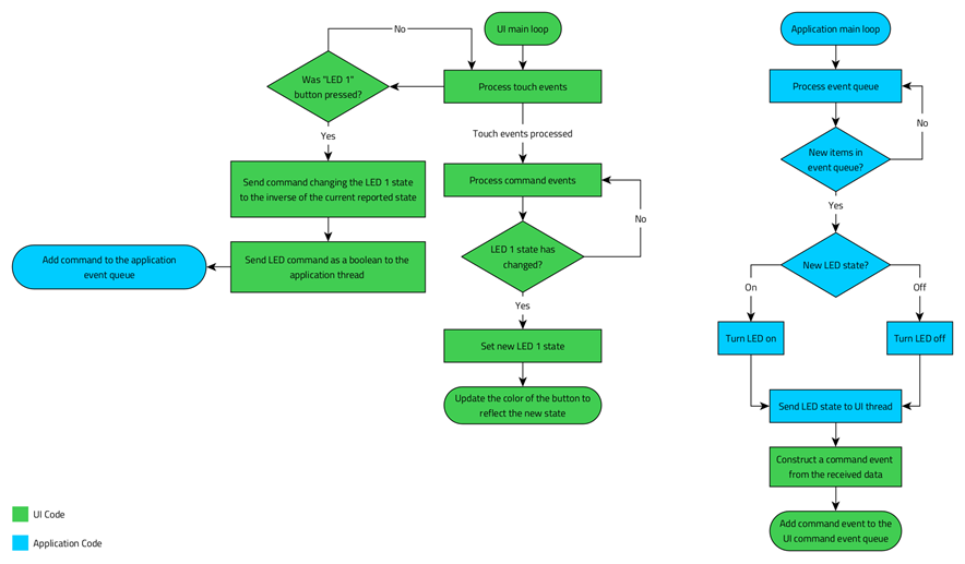
The backend enables the application's UI to communicate with the platform and get the required information from the hardware. In this case, the communicator gets the status of the on-board LED. The following diagram describes the workflow between the two components:
- Select and hold or right-click the source folder in the Project Explorer and select New > Class.
- Add UICommunicator to the Class name field. Rename the Header and Source to
uicommunicator.handuicommunicator.cpprespectively, and select Finish. - Open uicommunicator.h and modify it to look like the following:
#ifndef UICOMMUNICATOR_H
#define UICOMMUNICATOR_H

#include <qul/singleton.h>
#include <qul/property.h>
#include <qul/eventqueue.h>

struct UICommunicator : public Qul::Singleton<UICommunicator>
{
    friend struct Qul::Singleton<UICommunicator>;

    enum Command { LED1State };

    Qul::Property<bool> led1Status;

    void sendFromUI(Command command, bool commandData);
    void receiveToUI(Command command, bool commandData);

private:
    UICommunicator();
    UICommunicator(const UICommunicator &);
    UICommunicator &operator=(const UICommunicator &);
};

struct CommandEvent
{
    UICommunicator::Command command;
    bool commandData;
};

class CommandEventQueue : public Qul::EventQueue<struct CommandEvent, Qul::EventQueueOverrunPolicy_Discard, 10>
{
public:
    void onEvent(const CommandEvent &commandEvent);
};

namespace UI {
void sendToThread(bool led1Data);
}

#endif // UICOMMUNICATOR_H
The header declares the
UICommunicatorstruct, which inheritsQul::Singleton, enabling easy integration with UI code. For more information, refer to Singleton class reference.The header also declares the
Commandenumeration that defines a list of commands, and theCommandEventQueueto manage the queue. The enumeration enables communication between the UI and the application.UICommunicatordeclaresled1Statusproperty to indicate the status of the on-board LED. This property is accessible in the QML context, to determine the color of the button.The
UICommunicatorclass has thesendFromUIandreceiveToUIfunctions to send and receive commands. It also has theCommandEventQueueto communicate with the UI thread in a thread-safe way. Instead of callingreceiveToUIfrom the application thread, the commands are added to theCommandEventQueue. The Qt Quick Ultralite thread processes the queue by callingreceiveToUI. - Open uicommunicator.cpp and modify it to look like the following:
#include "uicommunicator.h"
#include "app_thread.h"

UICommunicator::UICommunicator()
{
    led1Status.setValue(false);
}

void UICommunicator::sendFromUI(Command command, bool commandData)
{
    QUL_UNUSED(command)

    App::sendToThread(commandData);
}

void UICommunicator::receiveToUI(Command command, bool commandData)
{
    switch (command) {
    case LED1State:
        led1Status.setValue(commandData);
        break;
    default:
        break;
    }
}

void CommandEventQueue::onEvent(const CommandEvent &commandEvent)
{
    UICommunicator::instance().receiveToUI(commandEvent.command, commandEvent.commandData);
}

static CommandEventQueue commandEventQueue;

void UI::sendToThread(bool led1Data)
{
    CommandEvent commandEvent;
    commandEvent.command = UICommunicator::LED1State;
    commandEvent.commandData = led1Data;
    commandEventQueue.postEvent(commandEvent);
}
The
UICommunicatorclass initializesled1Statustofalse. ItssendFromUI()member function sends a boolean value indicating the LED's new state to the application thread. ThereceiveToUI()member function uses the command argument to determine if the property must be updated.Next, the
CommandEventQueueclass overrides theonEvent()function, which callsreceiveToUI()on theUICommunicatorinstance with thecommandandcommandDataparameters. In addition, a static instance ofCommandEventQueueis created, which is used by theUI::sendToThread()function to post events.UI::sendToThread()constructs aCommandEventfrom the given boolean value and adds it to thecommandEventQueuefor processing. It is called from application thread when the LED's state is changed.
Create a Qt for MCUs CMSIS-Pack
A CMSIS-Pack is an IDE agnostic package containing information and files needed to setup Qt for MCUs application within the MCUXpresso IDE project.
- Create a CMSIS-Pack using the
qmlprojectexportertool.Add the
UICommunicatorinterface to the UI project:- Open
path/to/YourProject.qmlproject - Add the following inside
Project:InterfaceFiles { files: ["path/to/mcuxpresso/project/source/uicommunicator.h"] }
export QUL_ROOT=/path/to/QtMCUs/3.0.0
export QMLPROJECT_FILE=/path/to/YourProject.qmlproject
export PLATFORM_METADATA=$QUL_ROOT/lib/QulPlatformTargets_mimxrt1170-evkb-freertos_32bpp_Linux_armgcc-export.json
export BOARDDEFAULTS=$QUL_ROOT/platform/boards/nxp/mimxrt1170-evkb-freertos/cmake/BoardDefaults_32bpp.qmlprojectconfig
export CMSIS_EXPORT_DIR=/output/dir/of/your/choice

$QUL_ROOT/bin/qmlprojectexporter $QMLPROJECT_FILE --platform=mimxrt1170-evkb-freertos --toolchain=GCC --platform-metadata=$PLATFORM_METADATA --boarddefaults=$BOARDDEFAULTS --outdir=$CMSIS_EXPORT_DIR --project-type=cmsis
set QUL_ROOT=C:\path\to\QtMCUs\3.0.0 set QMLPROJECT_FILE=C:\path\to\YourProject.qmlproject set PLATFORM_METADATA=%QUL_ROOT%\lib\QulPlatformTargets_mimxrt1170-evkb-freertos_32bpp_Windows_armgcc-export.json set BOARDDEFAULTS=%QUL_ROOT%\platform\boards\nxp\mimxrt1170-evkb-freertos\cmake\BoardDefaults_32bpp.qmlprojectconfig set CMSIS_EXPORT_DIR=C:\output\dir\of\your\choice %QUL_ROOT%\bin\qmlprojectexporter.exe %QMLPROJECT_FILE% --platform=mimxrt1170-evkb-freertos --toolchain=GCC --platform-metadata=%PLATFORM_METADATA% --boarddefaults=%BOARDDEFAULTS% --outdir=%CMSIS_EXPORT_DIR% --project-type=cmsis - Open
- Import the created CMSIS package into the MCUXpresso IDE project:
- Go to CMSIS-Pack Manager perspective.
- In the Packs tab, select the Import Existing Packs... button.
- Navigate to the output folder specified to qmlprojectexporter. The pack file should be in the
CMSISfolder, named<YourProject>-mimxrt1170-evkb-freertos-<OS>-armgcc-cmsis.pack. Select Open. The pack should show up in the list of CMSIS-Packs. - Go back to Develop perspective.
- Select and hold or right-click on project name in Project Explorer.
- Go to SDK Management > Add Open-CMSIS Components.
- Select the following components:
- Graphics (Variant: Qt for MCUs)
- Platform DeviceLink library (Variant: FreeRTOS)
- Platform sources (Variant: FreeRTOS)
- Qt Quick Ultralite headers
- Qt Quick Ultralite libraries
- Project
- Qt for MCUs Application
- Graphics (Variant: Qt for MCUs)
- Select the small button next to the Qt for MCUs Application checkbox. This launches qmlprojectexporter, which exports the Qt Quick Ultralite application to the project.
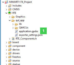
- Wait for the export to finish. You should see application.gpdsc in the project explorer as shown in the following image:
- Select Apply and save changes.
Configure the MCUXpresso IDE project
- Select your project and select File > Properties to make the following changes:
- Select C/C++ General > Paths and Symbols > Source Location and add the following to the list:
gt911vglite
- Add the following include paths to the C++ include directories list under C/C++ General > Paths and Symbols > Includes. Select Add to all configurations and Add to all languages. For this application, add the following include directories:
gt911from workspacevglite/incfrom workspacevglite/VGLite/rtosfrom workspacevglite/VGLiteKernelfrom workspacevglite/VGLiteKernel/rtosfrom workspace
- Select C/C++ General > Paths and Symbols > Symbols and add the following preprocessor definitions:
- For all configurations and languages:
BOARD_MIPI_PANEL_TOUCH_IRQ GPIO2_Combined_16_31_IRQnBOARD_MIPI_PANEL_TOUCH_IRQ_HANDLER GPIO2_Combined_16_31_IRQHandlerCPP_NO_HEAPThis disables the defaultmallocandfreeimplementations by introducing empty implementations incpp_config.cpp.FSL_RTOS_FREE_RTOSPRINTF_ADVANCED_ENABLE 0PRINTF_FLOAT_ENABLE 0SCANF_ADVANCED_ENABLE 0SCANF_FLOAT_ENABLE 0SKIP_SYSCLK_INITUSE_SDRAMSDK_I2C_BASED_COMPONENT_USED 1XIP_BOOT_HEADER_ENABLE 1XIP_EXTERNAL_FLASH 1XIP_BOOT_HEADER_DCD_ENABLE 1- Remove
__MCUXPRESSO
- For GNU C++
VGLITE_POINT_FILTERING_FOR_SIMPLE_SCALE
- For all configurations and languages:
- Select C/C++ Build > Settings > Tool Settings > MCU C++ Linker > Miscellaneous > Other objects. Change the order of the libraries in the list to be the following:
- libQulCore_cortex-m7-hf-fpv5-d16_Linux_armgcc_MinSizeRel.a
- libQulControlsTemplates_cortex-m7-hf-fpv5-d16_Linux_armgcc_MinSizeRel.a
- libQulControls_cortex-m7-hf-fpv5-d16_Linux_armgcc_MinSizeRel.a
- libQulShapes_cortex-m7-hf-fpv5-d16_Linux_armgcc_MinSizeRel.a
- libQulTimeline_cortex-m7-hf-fpv5-d16_Linux_armgcc_MinSizeRel.a
- libQulMonotypeUnicodeEngineShaperDisabled_cortex-m7-hf-fpv5-d16_Linux_armgcc_MinSizeRel.a
- libQulMonotypeUnicode_cortex-m7-hf-fpv5-d16_Linux_armgcc_MinSizeRel.a
- libQulPNGDecoderNull_cortex-m7-hf-fpv5-d16_Linux_armgcc_MinSizeRel.a
- libQulDeviceLink_mimxrt1170-evkb-freertos_Linux_armgcc_MinSizeRel.a
- libQulCore_cortex-m7-hf-fpv5-d16_Windows_armgcc_MinSizeRel.a
- libQulControlsTemplates_cortex-m7-hf-fpv5-d16_Windows_armgcc_MinSizeRel.a
- libQulControls_cortex-m7-hf-fpv5-d16_Windows_armgcc_MinSizeRel.a
- libQulShapes_cortex-m7-hf-fpv5-d16_Windows_armgcc_MinSizeRel.a
- libQulTimeline_cortex-m7-hf-fpv5-d16_Windows_armgcc_MinSizeRel.a
- libQulMonotypeUnicodeEngineShaperDisabled_cortex-m7-hf-fpv5-d16_Windows_armgcc_MinSizeRel.a
- libQulMonotypeUnicode_cortex-m7-hf-fpv5-d16_Windows_armgcc_MinSizeRel.a
- libQulPNGDecoderNull_cortex-m7-hf-fpv5-d16_Windows_armgcc_MinSizeRel.a
- libQulDeviceLink_mimxrt1170-evkb-freertos_Windows_armgcc_MinSizeRel.a
Note: Libraries must be in the order listed. Otherwise, the linker may complain about missing symbols due to the wrong linking order.
- Select C/C++ Build > Settings > Tool Settings > MCU C++ Linker > Miscellaneous > Linker flags and add
-specs=nosys.specs.Note: Be careful not add the flag to Other options(-Xlinker [option]) field. This will result in linker not picking it up correctly.
- Select Resource > Linked Resources. In the Linked Resources tab, select Variable Relative Location > MIMXRT1176xxxxx_cm7_flexspi_nor_sdram.ld and select the Edit... button. In the Edit Link Location copy the contents of Location field.
- Select C/C++ Build > Settings > Tool Settings > MCU C++ Linker > Managed Linker Script and clear the Manage linker script, and paste the content copied in the previous step to the Linker script field.
- Select C/C++ Build > Settings > Tool Settings > MCU C++ Linker > General} and clear the No startup or default libs option.
- After making the changes, select Apply and Close button.
- Select C/C++ General > Paths and Symbols > Source Location and add the following to the list:
- Remove source/FreeRTOSConfig.h from the project. The generated CMSIS pack already includes a working FreeRTOSConfig.h for the project.
- Open source/cpp_config.cpp and make the following changes:
- Add
#include <FreeRTOS.h> #include <portable.h> #include <task.h> - Replace all
malloc()andfree()calls withpvPortMalloc()andvPortFree()calls respectively.Note: Do not rename the function definitions inside
#ifdef CPP_NO_HEAP. - If you want, you can also replace the empty
malloc()andfree()implementations with calls to FreeRTOS memory allocation functions.
- Add
Finalize the application backend
- Open
source/<project-name>.cppand replace the contents with the following code:Note: Replace
YOUR_UI_APPwith exported UI application name.#include <app_thread.h> #include <YOUR_UI_APP.h> #include <qul/application.h> #include <qul/qul.h> #include <platforminterface/log.h> #include <FreeRTOS.h> #include <task.h> #include <board.h> static void Qul_Thread(void *argument); static void App_Thread(void *argument); int main() { Qul::initHardware(); Qul::initPlatform(); if (xTaskCreate(Qul_Thread, "Qul_Thread", 32768, 0, 4, 0) != pdPASS) { Qul::PlatformInterface::log("Task creation failed!.\r\n"); configASSERT(false); } if (xTaskCreate(App_Thread, "App_Thread", 200, 0, 4, 0) != pdPASS) { Qul::PlatformInterface::log("Task creation failed!.\r\n"); configASSERT(false); } vTaskStartScheduler(); // Should not reach this point return 1; } static void Qul_Thread(void *argument) { (void) argument; Qul::Application _qul_app; static struct ::YOUR_UI_APP _qul_item; _qul_app.setRootItem(&_qul_item); #ifdef APP_DEFAULT_UILANGUAGE _qul_app.settings().uiLanguage.setValue(APP_DEFAULT_UILANGUAGE); #endif _qul_app.exec(); } static void App_Thread(void *argument) { App::run(); } extern "C" { void vApplicationStackOverflowHook(TaskHandle_t xTask, signed char *pcTaskName) { (void) xTask; (void) pcTaskName; Qul::PlatformInterface::log("vApplicationStackOverflowHook"); configASSERT(false); } void vApplicationMallocFailedHook(void) { Qul::PlatformInterface::log("vApplicationMallocFailedHook"); configASSERT(false); } }main()initializes the board and creates the following two tasks:Qul_Threadto run UIApp_Threadto handle the LED commands, and signal UI to update the button color based on the LED status.
- Select and hold or right-click source folder and select New > Header File. Name it as
app_thread.hand add the following:#ifndef APP_THREAD_H_ #define APP_THREAD_H_ namespace App { void run(); void sendToThread(bool ledStatus); } // namespace App #endif /* APP_THREAD_H_ */ - Select and hold or right-click the source folder and select New > Source File. Name it as
app_thread.cppand add the following code:#include "app_thread.h" #include "uicommunicator.h" #include "board.h" #include <fsl_gpio.h> #include <FreeRTOS.h> #include <queue.h> namespace App { static QueueHandle_t appQueue = NULL; void run() { // enable SW7/WAKE UP button interrupt NVIC_SetPriority(BOARD_USER_BUTTON_IRQ, configLIBRARY_MAX_SYSCALL_INTERRUPT_PRIORITY); EnableIRQ(BOARD_USER_BUTTON_IRQ); USER_LED_INIT(0U); // initialize LED to be off appQueue = xQueueCreate(20, 1); bool ledState; while (true) { if (pdTRUE == xQueueReceive(appQueue, &ledState, portMAX_DELAY)) { if (ledState) USER_LED_ON(); else USER_LED_OFF(); UI::sendToThread(ledState); } } } void sendToThread(bool ledStatus) { if (appQueue) { xQueueSend(appQueue, &ledStatus, 0); } } } // namespace App extern "C" void BOARD_USER_BUTTON_IRQ_HANDLER(void) { GPIO_PortClearInterruptFlags(BOARD_USER_BUTTON_GPIO, 1U << BOARD_USER_BUTTON_GPIO_PIN); bool ledStatus = 0x1 ^ GPIO_PinRead(BOARD_USER_LED_GPIO, BOARD_USER_LED_GPIO_PIN); if (App::appQueue) xQueueSendFromISR(App::appQueue, &ledStatus, NULL); }This file defines a simple app thread and all its related functions. First,
appQueueis defined to store commands that toggle the board's LED state (on or off). TheApp::runfunction is the main loop of theapp_thread. It enables interrupts for the user button on the board, initializes one of the board LEDs to be off, and creates a queue for the thread. After this, the thread enters an infinite loop waiting for the commands to toggle the LED state. This status is then sent to UI (Qt Quick Ultralite) thread.Next, there's the
App::sendToThreadfunction which posts the given led state to theappQueue. Last, there is an IRQ handler for the user button. When the button is pressed, it checks the current state of the LED and posts an inverse of that state to theappQueue.
Your application is now ready. Build and flash it to the NXP i.MX RT1170 board to test that everything works as intended.
Note: If the application does not seem to respond to touch, try pressing the SW7/WAKEUP button on the board.
Available under certain Qt licenses.
Find out more.
