3D
When editing a 3D scene, you view the scene in the 3D view.
When you import 3D scenes from files that you exported from 3D graphics tools, you also import a scene camera, light, model, and materials. If your scene does not contain them, add the corresponding Qt Quick 3D components from Components >  > Qt Quick 3D > Qt Quick 3D.
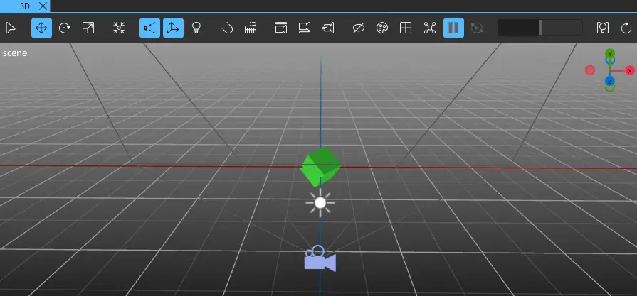
Use the 3D toolbar buttons to modify the 3D view, manipulate the 3D scene, and to access functionalities to transform 3D components. Transformation refers to moving, rotating, or scaling a component. The pivot of the component is used as the origin for transformations. Set a local pivot offset for a component in Properties to transform the component around a point other than its local origin. A line is drawn in the 3D view from the pivot point to the center of the component to provide a visual connection between them.
Note: To avoid transforming components by mistake while editing your scene, use the showing and hiding or the locking features in Navigator.
To refresh the contents of the 3D view, select P or select the  (Reset View) button.
The following video illustrates navigating in the 3D view and using the toolbar:
To learn the basics of using 3D in Qt Design Studio, take the 3D with Qt Design Studio course in Qt Academy.
Using the context menu in the 3D view
There is a context menu in the 3D view. To open it, right-click in the 3D view. From the context menu you can, for example:
- Create cameras, lights, and models.
- Delete components.
- Align camera views.

Controlling the 3D view camera
Toggling the camera mode
Change the projection of the view by switching between perspective camera and orthographic camera modes. When using the perspective camera mode, components that are far from the camera appear smaller than those nearby. In the orthographic camera mode, all components appear at the same scale irrespective of their distance from the camera. Both of them are free-form camera modes that you can use to orbit around the scene.
To toggle the camera mode, do one of the following:
- Select
 (Toggle Perspective/Orthographic Camera) to use the perspective camera mode.
 - Select
 to use the orthographic camera mode.
You can also toggle the camera mode by using the keyboard shortcut T.
Navigating in the 3D scene
Navigate the scene by panning, rotating, and zooming the 3D view camera:
- To pan, do one of the following and drag anywhere in the view to pan:
- Select and hold Alt (or Option on macOS) and middle mouse button.
- Select and hold right mouse button, and then select and hold left mouse button.
- Select and hold Shift and left mouse button.
- To orbit, select Alt and and drag anywhere in the 3D view to rotate the view.
- To zoom, use the mouse wheel or select Alt and right-click anywhere in the 3D view to zoom the view in or out as you drag up or down.
To zoom and focus the 3D view camera on a selected component, select  (Fit Selected) or select F.
The world axis helper (1) shows the direction of the world axes in the view. To point the 3D view camera at the currently selected component in the direction of an axis, select the axis. To point the camera at the opposite direction of the axis, select the dot at the end of the axis. If no component is selected, the camera is pointed at the world origin.
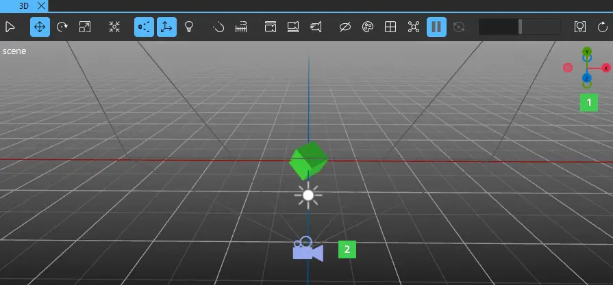
Use scene cameras (2) to view the View3D component from a specific angle in the 2D view while editing scenes. Drag a camera component to your scene from Components > Qt Quick 3D > Qt Quick 3D. For more information about using cameras in the scene and the available camera types, see Cameras.
Using the split view
Use the split view to view the scene from different points of view using the different viewport modes.
Use the split view to split the 3D view into multiple viewports. You can manipulate each of the viewports separately.
To view the scene in a split view, select  (Show Viewport Modes) and then select one of the viewport modes:
- The Single mode shows the scene in a single viewport.
- The Quad mode shows the scene from four different viewports.
- The 3 Left 1 Right mode shows the scene from four points of view using three smaller and one larger viewport.
- The 2 Horizontal mode shows the scene from two horizontal viewports.
- The 2 Vertical mode shows the scene from two vertical viewports.
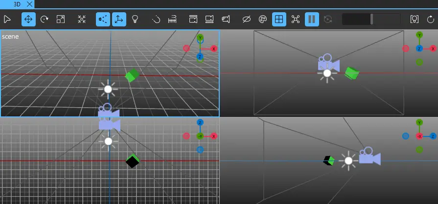
Select one of the viewports to make it the active viewport. The active viewport is marked with a blue frame. Use the world axis helper to change the point of view for each viewport independently. You can toggle the camera mode between the perspective and orthographic modes independently for each viewport. Navigate each split by panning, rotating, and zooming. To resize the viewports, drag the border between them.
Using the fly mode
Use the fly mode to move around freely in the 3D scene. To navigate the scene with fly mode, right-click and hold in the 3D view, and use the keyboard shortcuts to move around the scene:
| Key | Action |
|---|---|
| W or Up arrow | Move forward. |
| S or Down arrow | Move backward. |
| A or Left arrow | Move left. |
| D or Right arrow | Move right. |
| E or Page up | Move up. |
| Q or Page down | Move down. |
| Shift | Move faster. |
| Alt | Move slower. |
| Spacebar | Move to an object in the crosshairs. |
To adjust the movement speed, right-click and hold in the 3D view, and rotate the mouse wheel. Alternatively, select  in the 3D view toolbar to open the configuration dialog.
In the configuration dialog, you can:
- Adjust the movement speed of the camera with a slider.
- Set a value multiplier for the speed slider.
Toggling the camera view
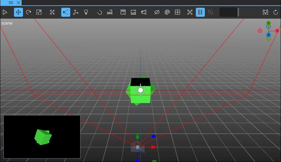
In the 3D view, you can show a small window displaying the camera view.
To toggle this view, select  and then one of the options:
| Hide Camera View | Never shows the camera view. |
| Show Selected Camera View | Shows the camera view of the selected camera. If no camera is selected, the camera view is hidden. |
| Always Show Camera View | Always shows the camera view of the camera that was selected last, even if no camera is currently selected. |
Using the global and the local orientation
In 3D view, you view the scene in global or local orientation mode.
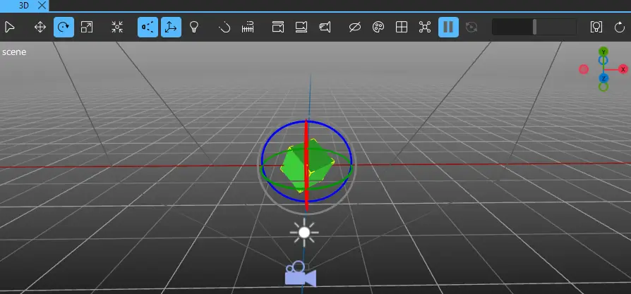
In global orientation mode, transformation of a selected component is presented with respect to the global space. For example, while the move tool is selected, selecting a cube will show its move gizmo aligned with the axes of global space. Dragging on the red arrow of the gizmo moves the component in the global x direction.
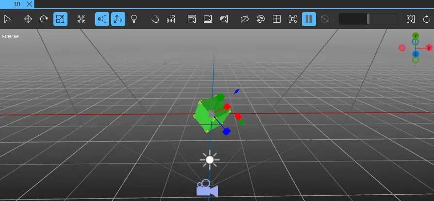
In local orientation mode, the position of a selected component is shown according to local axes specific to the selected component. For example, selecting a rotated cube will show its axes rotated, and not aligned with the axes of global space. Dragging on the red arrow of the gizmo moves the component in the local x direction in relation to the component.
To switch between local and global orientation, select  (Toggle Local/Global Orientation) or select Y.
Using the edit light
The edit light is an extra point light that can be used to illuminate the scene. To toggle the edit light on and off, select  or
or  (Toggle Edit Light) or select U.
For information about the available scene light types and their properties, see Lights.
Baking lights
Bake lights to light static elements in your scene. To bake lights, select  to open the Lights Baking Setup dialog. For more information, see Baking Lightmaps.
Selecting components
To move, rotate, or scale components in the scene, you need to select them first. Toggle the selection mode to determine how components are selected when you select them in the 3D view:
- Use the
 (Single Selection) mode to select a single component.
 - Use the
 (Group Selection) mode to select the top level parent of the component, so you can move a group of components simultaneously.
Alternatively, select Q to toggle the selection mode.
To multiselect, hold Ctrl and select the components you wish to select.
After selecting a component, you can apply the usual keyboard shortcuts applicable to your operating system, for example, Ctrl+C and Ctrl+V on Windows to copy-paste components.
Moving components

You can move components in relation to their coordinate system, along the x, y, or z axis or on the top, bottom, left, and right clip planes of the the 3D view.
To move components, select  or select W:
- To move components along the axes of the move gizmo, select the axis, and drag the component along the axis.
- To move components on a plane, drag the plane handle of the move component on the plane.
- To move components freely in the 3D view, drag the gray handle at the center of the move gizmo.
Rotating components
To rotate components, select  or select the E key:
- To rotate a component around its rotation gizmo, drag the axis ring in the direction you want to rotate the component in.
- To freely rotate the component, drag the inner center circle of the gizmo.
Scaling components
Úse the scale handles to adjust the local x, y, or z scale of a component. You can adjust the scale across one, two, or three axes, depending on the handle.
To scale components, select  or select the R key:
- To adjust the scale across one axis, drag the scale handle attached to the axis.
- To adjust the scale across a plane, drag the plane handle of the component.
- To uniformly scale a component across all axes, drag the gray handle at the center of the component.
Snapping
With snapping turned on, the objects in the 3D view snap to certain intervals during transformation (move, rotate, scale).
Toggle snapping in the following ways:
- Select
 in the 3D view toolbar.
 - Hold down the Ctrl key.
With snapping turned on, select and hold Shift to snap objects to one tenth of the specified snap interval.
Configuring snapping
To edit the snapping settings, select  in the 3D view toolbar to open the configure dialog.
In the configure dialog, you can do the following:
- Turn snapping on and off separately for the different transformations (move, rotate, scale).
- Set snap intervals for the transformations.
Note: Changing the snap interval for the position also changes the grid line intervals.
Note: All the grid lines might not be visible depending on the zoom level in the 3D view.
- Select Absolute Position to snap to absolute values. Clear the checkbox to use relative values.The absolute snapping aligns the object with the grid, while the relative snapping moves the object in fixed intervals without changing its alignment. For example, if you have an object that is slightly off the grid and you want to snap it to the grid, use the absolute snapping. If you want to move the object by a certain distance without affecting its orientation, use the relative snapping.
Aligning views and cameras
To align a camera to the 3D view:
- Select a scene camera in the 3D or Navigator view.
Note: If you don't have a camera selected, the most recently selected camera is aligned to the view.
- In the 3D view, select
 .
.
This moves and rotates the scene camera to show the same view as the current view in the 3D view.
To align the 3D view to a camera:
- Select a scene camera in the 3D view or Navigator.
Note: If you don't have a camera selected, the view is aligned to the most recently selected camera.
- In the 3D view, select
 .
.
This moves and rotates the 3D view to show the same view as the selected scene camera.
Toggling visibility
To toggle the visibility of objects in the 3D view, select in the toolbar. This opens a menu with the following options:
| Action | Description | Keyboard shortcut |
|---|---|---|
| Show Grid | Toggles the visibility of the helper grid. | G |
| Show Look-at | Toggles the visibility of the edit camera look-at indicator. | L |
| Show Selection Boxes | Toggles the visibility of selection boxes for selected 3D objects. | B |
| Show Icon Gizmos | Toggles the visibility of icon gizmos for object such as cameras, lights, and particle systems. | I |
| Always Show Camera Frustums | Toggles between always showing the camera frustum and showing it only for cameras selected in the 3D view. | C |
| Always Show Particle Emitters and Attractors | Toggles between always showing the particle emitter and attractor visualizations and only showing them when the emitter or attractor is selected in the 3D view. | M |
Changing colors
To change the 3D view background or grid color, select  in the toolbar. This opens a menu with the following options:
| Action | Decription |
|---|---|
| Select Background Color | Select a color for the background. |
| Select Grid Color | Select a color for the grid. |
| Use Scene Environment | Sets the 3D view to use the scene environment or skybox as background color. Note: When Use Scene Environment is selected, a 3D scene that doesn't have a View3D component, uses the scene environment of the previous View3D for rendering the scene. |
| Reset Colors | Resets the background and grid colors to the default colors. |
Particle editor
The particle editor tools help you preview your particle systems in the 3D view. You can select one particle system to preview at a time.
To preview a particle system in the 3D view:
- Select a particle system in the Navigator or 3D view.
- In the 3D view, select
 to activate particle animation. Now you can see the particle animation in the 3D view.
You can pause the particle animation by selecting  . When the animation is paused, use
  to manually seek forward or backward in the particle animation.
Using viewport shading
Use Viewport Shading to change the rendering of the materials to only reflect a particular aspect of the overall rendering process. Use shading also as a debugging tool to understand why a material looks the way it does. In split view, view the scene using different shading properties in each split.
To use the Viewport Shading, right-click the 3D view to open the context menu, select Viewport Shading and then select Wireframe, one of the material properties, or Reset All Viewports.
Select Wireframe to only show the edges of the objects in the scene.
Select one of the material properties available for shading:
| Property | Description |
|---|---|
| Base Color | Shows only the base color of a material passed through without any lighting. |
| Roughness | Shows only the roughness of a material passed through as an unlit greyscale value. |
| Metalness | Shows only the metalness of a material passed through as an unlit greyscale value. |
| Normals | Shows only the interpolated world space normal value of the material mapped to an RGB color. |
| Ambient Occlusion | Shows only the ambient occlusion of the material. |
| Diffuse | Shows only the diffuse contribution of the material after all lighting. |
| Specular | Shows only the specular contribution of the material after all lighting. |
Select Reset All Viewports to reset the shading of the scene in all of the splits.
Available under certain Qt licenses.
Find out more.
