Screenshot Verification Point
To open the Screenshot Verification Point dialog, right-click a failed screenshot verification in the Test Results view and select View Differences in the context menu. For an alternative way to open the dialog, see Setting Masks.
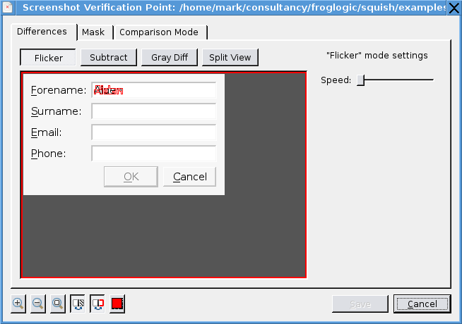
Use the buttons in the dialog to zoom into and out of the screenshot or to restore in to its original size, to show or hide the mask or highlighting (i.e., show or hide a red outline around differences), or to open a color chooser for selecting the highlighting line color.
Click the Save button to save the settings for the current screenshot or the Cancel button to close the dialog without saving any changes.
The Differences tab shows the differences between the expected and actual image. This tab offers four different ways to view the differences, with the default being Flicker view where the expected and actual images are shown alternately (and with differences outlined in red). The flicker speed can be set using the control on the right.
The Differences tab's Subtract view shows the differences by removing all the common pixels and just leaving those that differ between the two images. The way the subtraction works can be influenced by changing the HSV (Hue, Saturation, Value) color settings, and by checking or unchecking the Invert checkbox.
The Differences tab's Gray Diff view shows the differences by removing all the common pixels and just leaving those that differ between the two images. The way the differencing works can be influenced by changing the Contrast setting, and by checking or unchecking the Invert checkbox.
The Differences tab's Split View shows the left half of the expected image and the right half of the actual image with a vertical slider inbetween which can be used to vary the proportions to show more of one and less of the other.
The dialog's Mask tab shows the expected and actual images. It also provides Mask Tools (in the form of buttons at the right hand side of the dialog) for Add Positive Mask, Add Negative Mask, Mask Highlighted Differences, and Remove Mask. Most of these buttons are only enabled if the global Show/Hide Mask toggle toolbutton is pressed.
Add Positive Mask and Add Negative Mask allow you to mark a rectangular region of the expected image, marking it to be either an interesting area, or an uninteresting one (for the purposes of verification).
Mask Highlighted Differences makes sense only if there is an actual image to compare with the expected one, and they differ somehow. Then, clicking this button will will highlight and create a mask based on those differences.
The dialog's Comparison Mode tab is used to set the comparison mode. By default Strict mode is used which does a straight pixel-by-pixel comparison. If Strict mode is too strict there more tolerant modes available as documented below.
Comparison Modes
Strict Comparison Mode
The Strict mode is a pixel by pixel comparison which offers no additional configuration options:
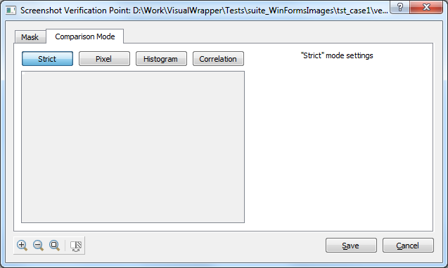
Pixel differences can occur which are not noticeable by the human eye due to various factors (graphics card drivers and hardware, operating system, anti-aliasing, etc.) which makes the "Strict" mode unsuitable at times.
Fuzzy Pixel Comparison Mode
The Pixel comparison mode compares the color of corresponding pixels of two images having the same dimensions.
It presents the images differences in percentage. For example, a difference of 10% means that 10% of the pixels are different.
The algorithm has a Allowed failure threshold parameter that defines the criterion by which images are considered to be equal. Therefore, for the example of 10% different pixels, a threshold of 11% would consider both images to be equal:
![]()
The Max. Color Difference parameter is useful when you compare images that have different shades (not detectable by eye). This can happen to screenshots that are taken on machines that have different video adapters. The screenshots look very similar and you want to ignore tiny color differences they have.
Technically speaking, Max. Color Difference is the distance between two colors in 3D (RGB) color space (also see Euclidean distance).
For example you have two pixels with the following colors: (0, 0, 0) and (1, 1, 1) - one is absolutely black and another is almost black (you cannot distinguish their colors by eye). The difference between these two colors can be calculated with the following formula:
diff = sqrt((r2 - r1)^2 + (g2 - g1)^2 + (b2 - b1)^2)
Here r, g and b are red, green and blue color component values. So for our example the calculation would be:
diff = sqrt(1 + 1 + 1) = ~1.73
Also, the color difference between black and white colors is ~441.67. So, if you want to compare solid black image with white one and set the Max Color Difference to be 441.67, result will be positive, i.e., images match.
In the Test Results view you may find this additional information in failed screenshots:
...(difference: 0.7976%, max. color difference: 80.6040)
The "difference: 0.7976%" part denotes the number of pixels that are different in percent. In this example it is 0.7976% and not 79.76%, i.e., the relative number is very small, less than one percent. For example, if you compare images of 10x10px, and only one pixel is different, you will get 1% difference.
The "max. color difference: 80.6040" part denotes the largest pixel color difference - in this case 80.6040. So if you set Max Color Difference to be 81, your test will pass, because all the pixels that failed previously will be considered equal then.
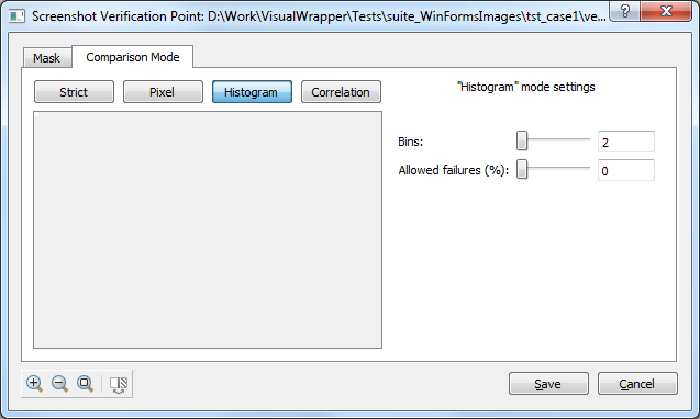
Histogram Comparison Mode
Histogram mode is based on comparing image color histograms. It is useful for cases when images are resized/scaled or rotated, so that their color profile remains the same or is not changed much:
How it works:
- Divide the color range (0-255) of each color component (RGB) of every pixel by the number of Bins (or baskets) and calculate the number of pixels that fall into each bin based on their color characteristics.
- Divide the total number of pixels in the image by the number of pixels in each bin to get "normalized values" (which allows comparison even if they have different sizes). These respective values are put back into the corresponding bins.
- The values of all corresponding bins are subtracted from another and the resulting values summed up. This value represents the difference of the images.
This mode lets you configure the number of Bins and Allowed failures (threshold in percent), which represents the maximum difference between two images for which they are still considered to be "equal".
Correlation Comparison Mode
The Correlation mode measures the similarity between two images as a statistical "correlation" coefficient based on functions originally stemming from the signal processing domain. The degree of similarity will be given in a percentage whereas 0% could roughly be labeled as "no similarity" and 100% as "perfect similarity".
The comparison is done based on gray values after mapping images of different sizes to the same scale. Unlike the Strict Comparison mode, this mode is therefore potentially able to cope with screenshots of applications running on systems with different screen resolutions.
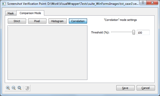
Use the Threshold configuration parameter to set the minimum correlation coefficient expected to consider the images to be equal. Two sets of sample images are given below to convey an assessment of calculated correlation values:
- The correlation between
 and
and  s 99.4614%. Note the different size and missing keyboard accelerator of the right button.
 - The correlation between and
 is 13.8309%. The screenshots have not much in common besides a few bright pixels in the center.
Setting Masks
When comparing screenshots, it is possible that the expected image contains more information than we need in our verification. We can mask parts of this image by either creating aPositive Mask, where the region outside the mask is ignored, or a Negative Mask, where the region inside the mask is ignored. The masking is done before the images are compared.
It is possible to set the Mask for a screenshot verification point before running a test (or between test runs), or when there is no failed screenshot test in the Test Results view, so no View Differences context menu item. This is done by clicking the VPs tab in the Test Suites view's Test Case Resources list and then clicking (or double-clicking depending on your settings) the image verification point whose Mask you want to modify. This will result in the Verification Point being shown, along with a tiny Edit Verification Point button. Click this button to invoke the Screenshot Verification Point dialog. The dialog will pop up with only two tabs, Mask and Comparison Mode—the Differences tab does not appear because the only image available is the expected image. The Mask tab can be selected, to see a GUI like the following screenshot.
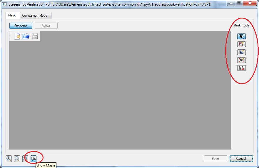
From here, we can insert, modify and remove positive and negative masks. A Positive Mask appears transparent, but the region outside the rectangle is marked red. A Negative Mask appears as a blue rectangle. It does not make sense to have both kinds of masks in the same verification point, unless they overlap somehow.
© 2025 The Qt Company Ltd.
Documentation contributions included herein are the copyrights of
their respective owners.
The documentation provided herein is licensed under the terms of the GNU Free Documentation License version 1.3 as published by the Free Software Foundation.
Qt and respective logos are trademarks of The Qt Company Ltd. in Finland and/or other countries worldwide. All other trademarks are property
of their respective owners.
